Full-duplex radio frequency echo cancellation

a radio frequency echo and full-duplex technology, applied in the field of full-duplex radio frequency echo cancellation, can solve the problems of “blinding” or complete saturation of the receiver, affecting the optimal performance of the rfid system, and affecting the efficiency of the transceiver

Active Publication Date: 2005-04-21
SYMBOL TECH LLC
View PDF3 Cites 72 Cited by
  • Summary
  • Abstract
  • Description
  • Claims
  • Application Information

AI Technical Summary

Problems solved by technology

A problem that arises is that optimal performance of RFID systems is often hampered by the reflection and coupling which inevitably occur in RF transceivers, in which a significant portion of the transmitted interrogation signal is reflected by the antenna and objects in the environment into the receiving portion of the transceiver.
A high VSWR interferes with efficient transceiver performance and may even result in a “blinding” or complete saturation of the receiver.
Transceivers designed to minimize VSWR are often unacceptable because of their high cost in terms of size and power, especially in the context of mobile devices.

Method used


Image

  • Full-duplex radio frequency echo cancellation
  • Full-duplex radio frequency echo cancellation
  • Full-duplex radio frequency echo cancellation

Examples


Embodiment Construction

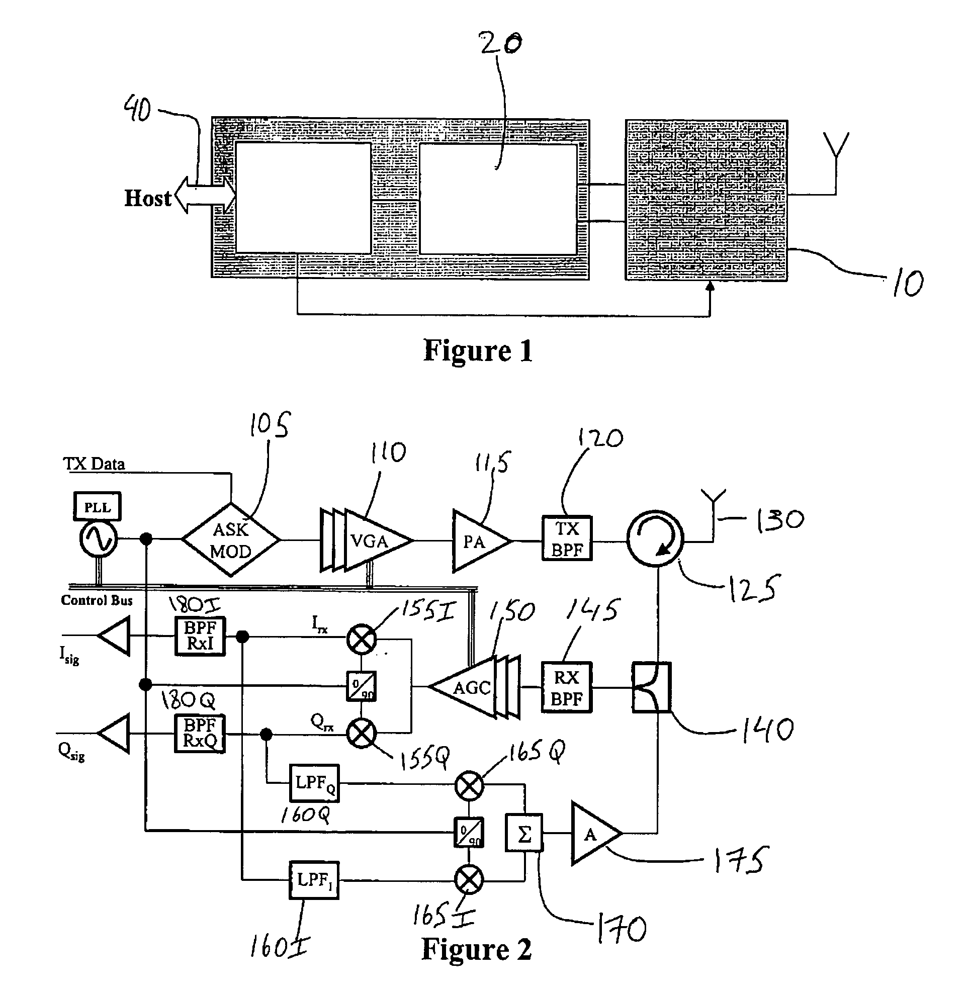
[0014]FIG. 1 illustrates the basic components of an RFID system 1, in which RF “tags” located on objects in the environment may reflect radio waves originating from a transceiver 10 in a pre-determined bit pattern and data rate via the principle of backscatter radiation. These reflections may be received by the transceiver 10, stripped of their carrier signal and converted into in-phase (“I”) and quadrature (“Q”) components. These components may then be independently digitized and sent to a base-band processor 20 for bit decoding. This decoded information may then be sent on to a reader control 30 which may perform such processes as error correction, command interpretation, and management of access to the RF channel. A host interface 40 performs filtering operations and translation of the results of the reader control 30 into a format intelligible to the host, and likewise translates host requests into a format intelligible to the reader control 30.

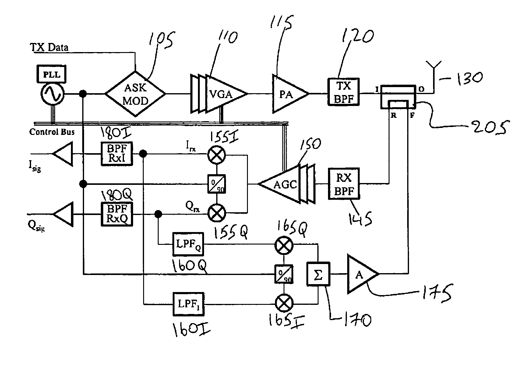
[0015]FIG. 2 shows an exemplary e...


PUM


Abstract

A system comprising a transmitter element creating an interrogation signal and transmitting the interrogation signal and a receiver element receiving a reflection signal of the interrogation signal and combining the reflection signal and a feedback signal to cancel at least a portion of radio frequency echo signals in the reflection signal.

Description

BACKGROUND [0001] Radio frequency identification (“RFID”) systems are used in a plethora of commercial contexts requiring a unique identification system for large numbers of items. Such contexts include everything from department store inventory and check-out systems to the tracking of military supplies to and from the front lines. Similar in utility to bar code technology, RFID systems are often preferred due to their increased range, lack of a line of sight requirement between a tag and its reader and the high multi-tag throughput of RFID readers (i.e., RFID readers may read many tags in their large field of view at very high transport speeds). [0002] A problem that arises is that optimal performance of RFID systems is often hampered by the reflection and coupling which inevitably occur in RF transceivers, in which a significant portion of the transmitted interrogation signal is reflected by the antenna and objects in the environment into the receiving portion of the transceiver. ...

Claims


Application Information

Patent Timeline
Patent Type & Authority Applications(United States)
IPC IPC(8): G06K7/00H04B1/52
CPCH04B1/525G06K7/0008
Inventor DURON, MARKBRIDGELALL, RAJ
Owner SYMBOL TECH LLC
Why Eureka
Try Eureka