Spectroscope

a spectroscope and spectrometer technology, applied in the field of spectroscopes, can solve the problems of unstable accuracy of wavelength measurement by a spectroscope, difficult to keep a constant temperature, and inability to apply the above-described temperature compensation technology to spectroscopes of other various types, and achieve the effect of reducing the drift of spectral images

Inactive Publication Date: 2005-04-28
NIKON CORP
View PDF2 Cites 11 Cited by
  • Summary
  • Abstract
  • Description
  • Claims
  • Application Information

AI Technical Summary

Benefits of technology

[0007] An object of the present invention is to provide a spectroscope equipped with a temperature compensation mechanism capable of reducing a drift of spectral images in the wavelength dispersion direction due to a change in the environmental temperature reliably irrespective of the form of the spectroscope.

Problems solved by technology

However, since the accuracy of wavelength measurement by a spectroscope is likely to be unstable due to influence of a change in the environmental temperature, the environmental temperature is kept constant in principle, when a spectroscope is used.
However, depending on the environment, it is sometimes difficult to keep a constant temperature.
Therefore, it is impossible to apply the above-described temperature compensation technologies to spectroscopes of other various types.
If those technologies are applied to a spectroscope of a different scheme by any means, the structure of the spectroscope will be complicated.

Method used


Image

  • Spectroscope
  • Spectroscope
  • Spectroscope

Examples


Embodiment Construction

[0019] In the following, an embodiment of the present invention will be described in detail with reference to the drawings.

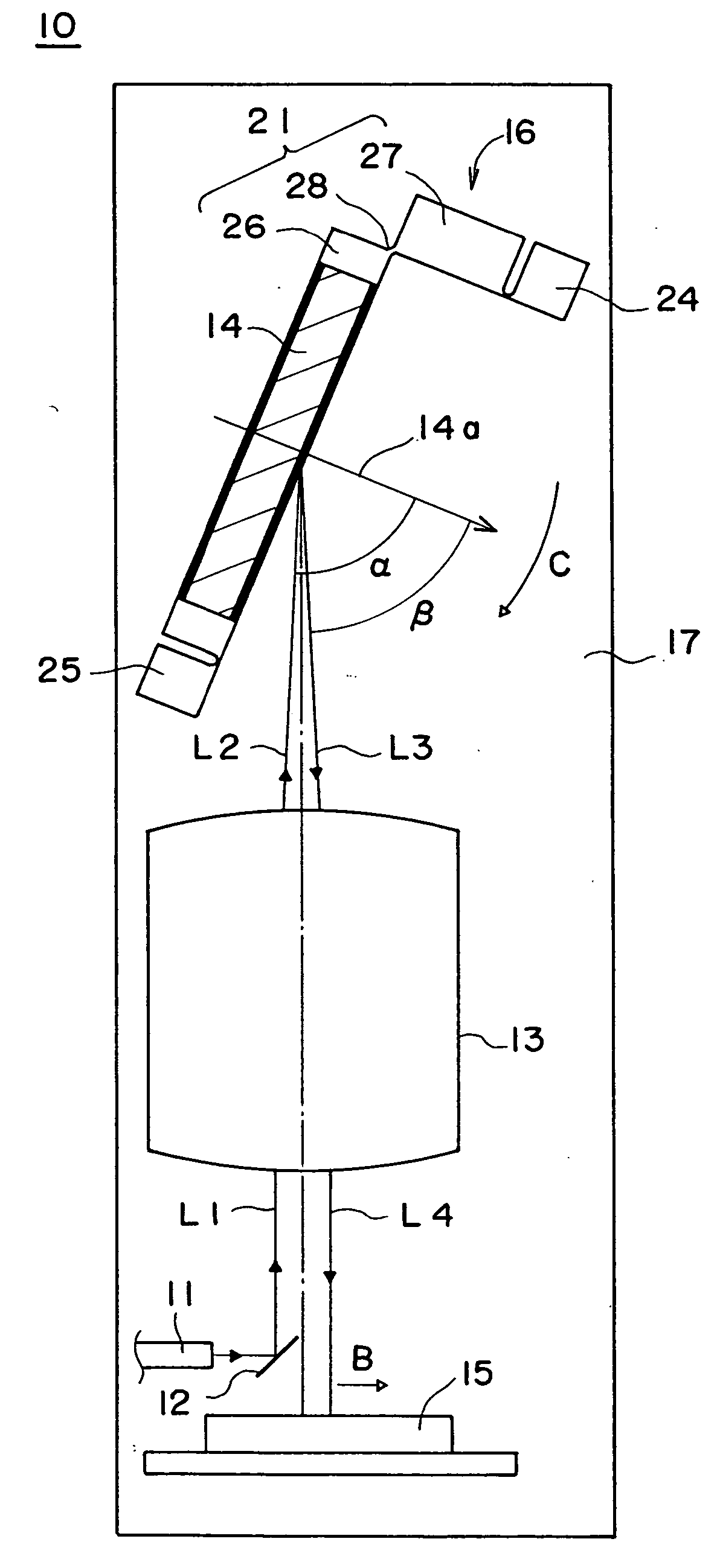
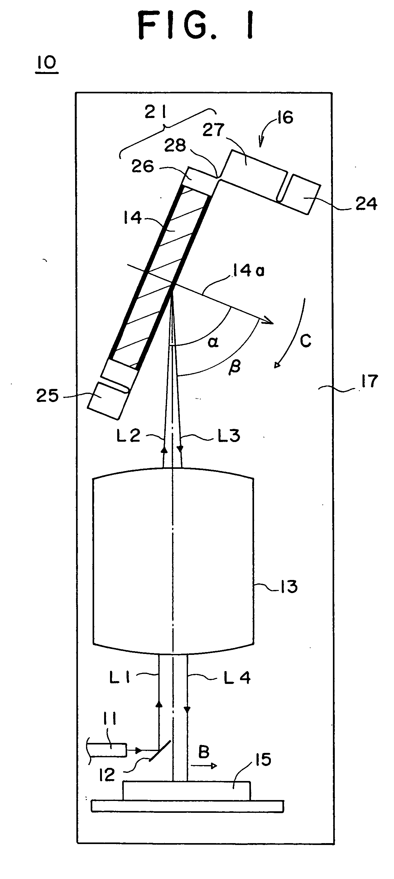
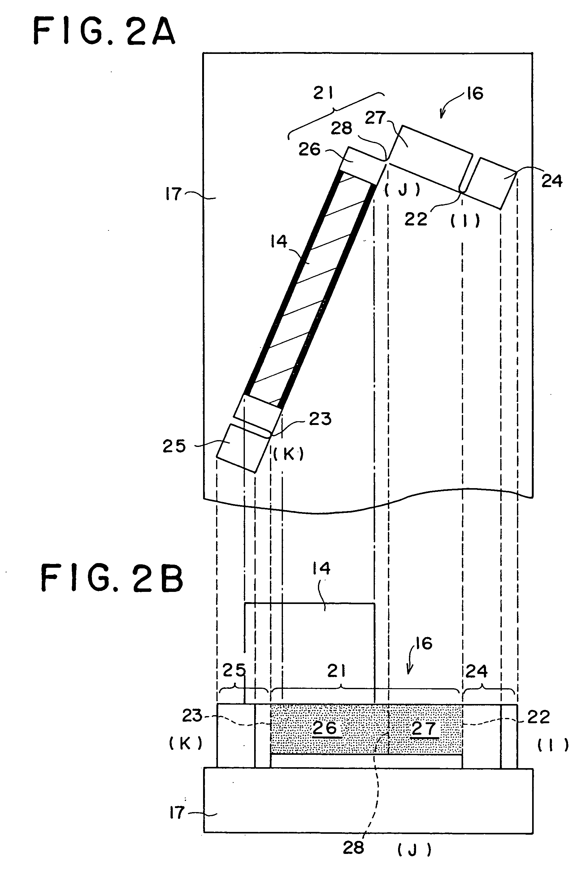
[0020] As shown in FIG. 1, a spectroscope 10 according to this embodiment is composed of an optical fiber 11, a mirror 12, a Littrow lens 13, a grating 14, a one-dimensional line sensor 15, a grating mount 16 and a base member 17. In addition, a light source that is not shown in the drawing is provided in the upstream of the optical fiber 11. Among the optical elements (11 to 15) that constitute the spectroscope 10, the optical fiber 11, the mirror 12, the Littrow lens 13 and the one-dimensional line sensor 15 are disposed on the base member 17. The grating 14 is disposed on the grating mount 16, which is disposed on the base member 17.

[0021] The spectroscope 10 of this embodiment is a spectroscope having a temperature compensation function, and it can be used under the environmental temperature range of −20° C. to +60° C.

[0022] Firstly, the structure and the...


PUM


Abstract

A spectroscope is equipped with a temperature compensation mechanism that can reliably reduce a drift of a spectral image in the wavelength dispersion direction caused by a change in the environmental temperature irrespective of the form of the spectroscope. The spectroscope is provided with a first support member 17 that integrally supports an incidence member 11, a collective optical system 13 and a detection element 15, a second support member 21, made of a material different from the first support member, that supports a wavelength dispersion element 14, and a transmission member 24, 25 that transmits a contraction/expansion amount of the first support member to the second support member when environmental temperature changes. The second support member includes a deformation member 28 that elastically deforms, when environmental temperature changes, in accordance with a difference between its own contraction/expansion amount and the contraction/expansion amount of the first support member and a rotation member 26 that rotates minutely in accordance with elastic deformation of the deformation member. The said wavelength dispersion element is mounted on the rotation member in such a way that its wavelength dispersion direction is oriented perpendicular to the axial direction of the rotation member.

Description

TECHNICAL FIELD [0001] The present invention relates to a spectroscope that utilizes a wavelength dispersion element such as a grating or a prism. BACKGROUND ART [0002] Spectroscopes utilizing a wavelength dispersion element have been widely used in various fields such as physical analysis or chemical analysis. However, since the accuracy of wavelength measurement by a spectroscope is likely to be unstable due to influence of a change in the environmental temperature, the environmental temperature is kept constant in principle, when a spectroscope is used. As long as the environmental temperature is kept constant, a drift of a spectral image of the light incident on the spectroscope in the wavelength dispersion direction can be almost avoided and the accuracy of wavelength measurement by the spectroscope can be made stable. [0003] However, depending on the environment, it is sometimes difficult to keep a constant temperature. In view of this, in recent years it has been desired to d...

Claims


Application Information

Patent Timeline
Patent Type & Authority Applications(United States)
IPC IPC(8): G01J3/02G01J3/18
CPCG01J3/02G01J3/0202G01J3/18G01J3/0286G01J3/0291G01J3/0208
Inventor KATSUNUMA, ATSUSHI
Owner NIKON CORP
Why Eureka
Try Eureka