Apparatus for reducing ambient light into an optical print scanner

Active Publication Date: 2005-05-05
HID GLOBAL CORP
View PDF6 Cites 8 Cited by
  • Summary
  • Abstract
  • Description
  • Claims
  • Application Information

AI Technical Summary

Benefits of technology

[0008] A light shroud preventing light from entering at specific angles can reduce or eliminate the effects of ambient light on an optical fingerprint scanner while allowing sufficient access to the platen by a user. The inventors recognized that there is a limited

Problems solved by technology

The inventors recognized that there is a limited range of angles at which ambient light can enter the prism, contact the illumination system and be reflecte

Method used


Image

  • Apparatus for reducing ambient light into an optical print scanner
  • Apparatus for reducing ambient light into an optical print scanner
  • Apparatus for reducing ambient light into an optical print scanner

Examples


Example

[0023] The present invention will be described with reference to the accompanying drawings. The drawing in which an element first appears is typically indicated by the leftmost digit(s) in the corresponding reference number.

DETAILED DESCRIPTION OF THE INVENTION

[0024] While specific configurations and arrangements are discussed, it should be understood that this is done for illustrative purposes only. A person skilled in the pertinent art will recognize that other configurations and arrangements can be used without departing from the spirit and scope of the present invention. It will be apparent to a person skilled in the pertinent art that this invention can also be employed in a variety of other applications.

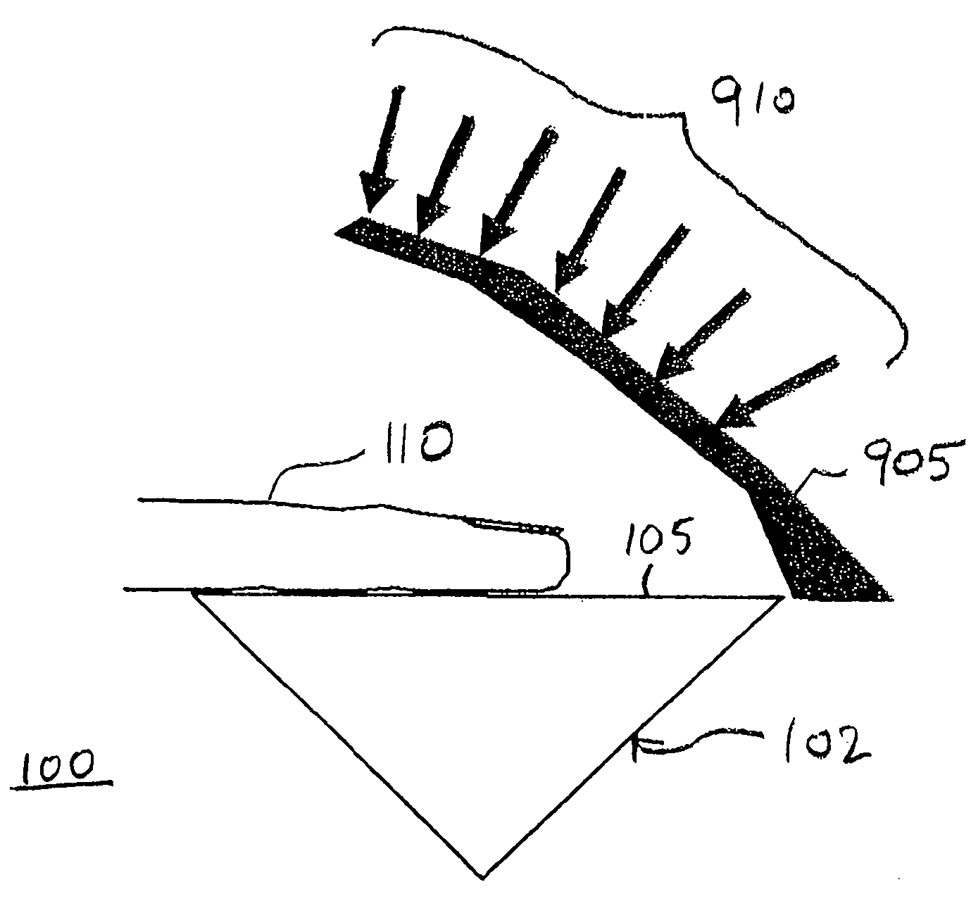
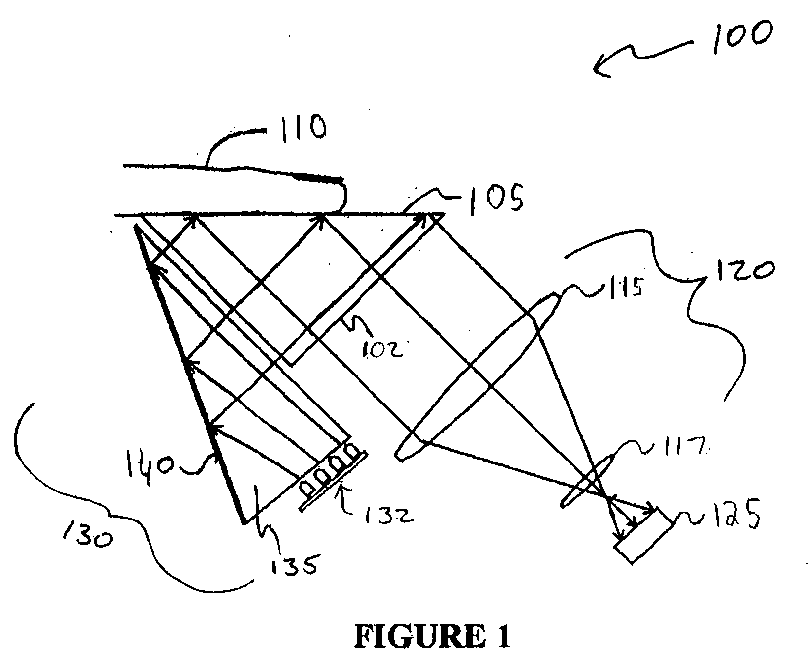
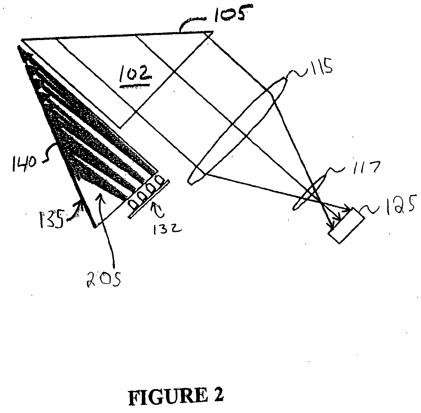
[0025]FIG. 1 shows a livescan fingerprinting system 100. Fingerprinting system 100 includes a prism 102 having a platen surface 105, an optical system 120, a camera 125, and an illumination system 130. Optical system 120 includes at least one optical element, such as lens 11...


PUM


Abstract

A light shroud reduces or eliminates the effects of ambient light on an optical fingerprint scanner. Because of the geometry of a prism used in the scanner, ambient light from only certain incidence angles can interfere with an image produced by the scanner. The light shroud blocks this ambient light entering the system at angles which allow the light to interfere with the illumination system or camera. In an embodiment, the light shroud can be closed to act as a cover, protecting the platen surface.

Description

CROSS-REFERENCE TO RELATED APPLICATIONS [0001] This application claims the benefit of U.S. Provisional Application No. 60 / 515,448, filed Oct. 30, 2003, hereby incorporated by reference herein in its entirety.BACKGROUND OF THE INVENTION [0002] 1. Field of the Invention [0003] The present invention relates to the field of biometrics. More specifically, the present invention relates to live scanning of prints. [0004] 2. Background Art [0005] Print imaging systems can capture images of prints on thumbs, fingers, palms, toes, feet, and / or hands. Such print imaging systems are also referred to as live scanners, live print scanners, or simply scanners. Live scanners often include a light source, platen and camera. An object having a print pattern is placed on the platen. A platen is often one planar surface of a prism. The light source illuminates the platen. The camera captures an image of a print placed on the platen. [0006] Many live print scanners utilize the optical principle of frust...

Claims


Application Information

Patent Timeline
IPC IPC(8): G02FG06K9/74
CPCG06K9/00046G06V40/1324
Inventor CARVER, JOHN F.MCCLURG, GEORGE W.
Owner HID GLOBAL CORP
Why Eureka
Try Eureka