Snap-through thermal actuator

a thermal actuator and actuator technology, applied in thermal electric motors, electrical appliances, printing, etc., can solve the problems of low cost of micro-electromechanical devices, inability to reliably generate electrostatic forces, and severe limits on the formulation of inks and other liquids

Inactive Publication Date: 2005-05-12
EASTMAN KODAK CO
View PDF21 Cites 2 Cited by
  • Summary
  • Abstract
  • Description
  • Claims
  • Application Information

AI Technical Summary

Benefits of technology

[0016] It is therefore an object of the present invention to provide a snap-through thermal actuator which provides large force magnitudes and accelerations and which does not require excessive peak temperatures.

Problems solved by technology

Micro-electromechanical devices are potentially low cost, due to use of microelectronic fabrication techniques.
This temperature exposure places severe limits on the formulation of inks and other liquids that may be reliably emitted by thermal ink jet devices.
However, the electrostatic forces that can be reliably generated are weak and membrane sticking problems can limit the long term usefulness.
In operation, an excessive acceleration of the mounting structure of the beam causes it to snap through to the opposite buckle state, opening or closing an electric switch.
Upon heating the cantilevered microbeam bends away from the layer having the higher coefficient of thermal expansion, deflecting the free end and causing liquid drop emission.

Method used


Image

  • Snap-through thermal actuator
  • Snap-through thermal actuator
  • Snap-through thermal actuator

Examples


Embodiment Construction

[0051] The invention has been described in detail with particular reference to certain preferred embodiments thereof, but it will be understood that variations and modifications can be effected within the spirit and scope of the invention.

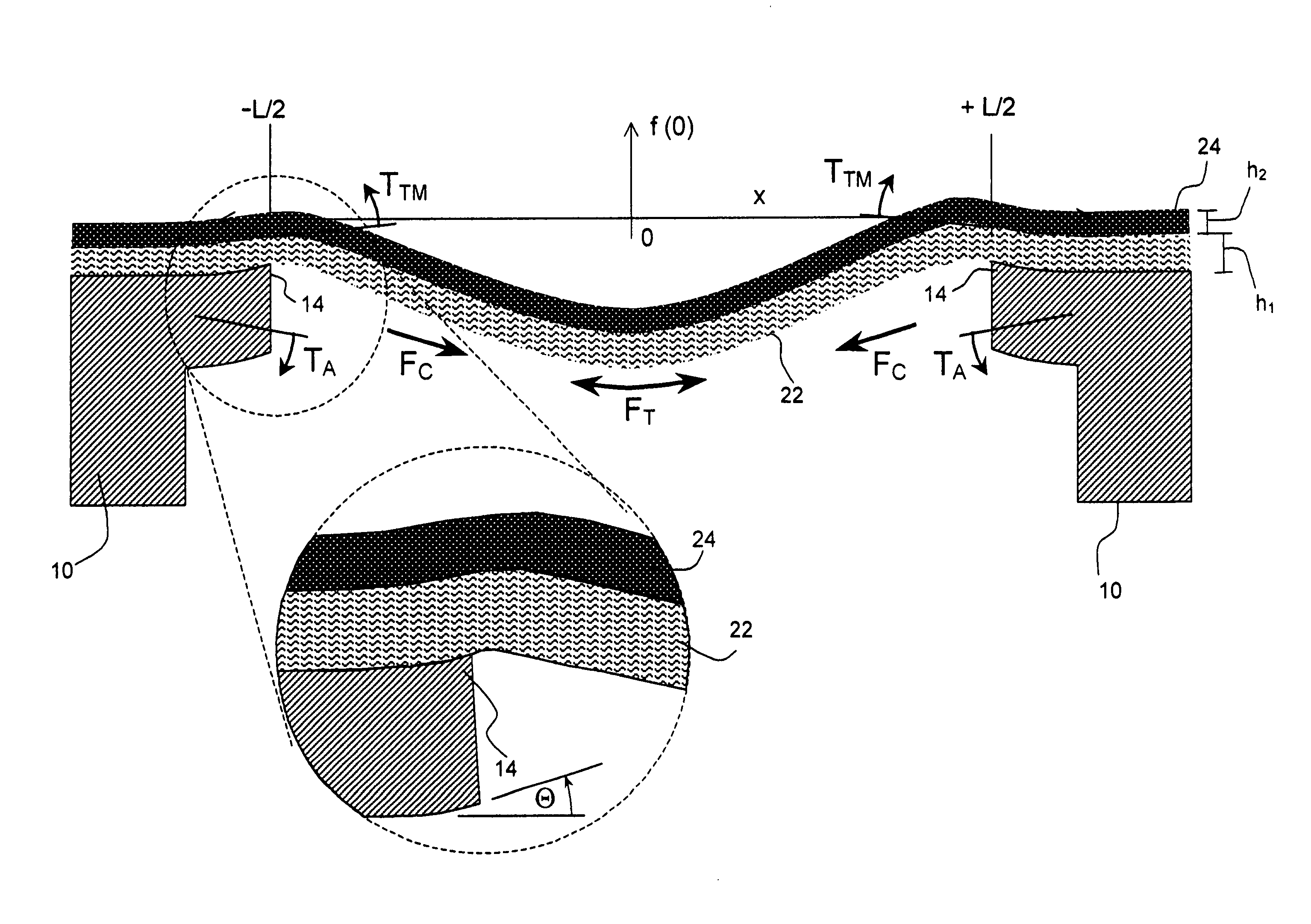
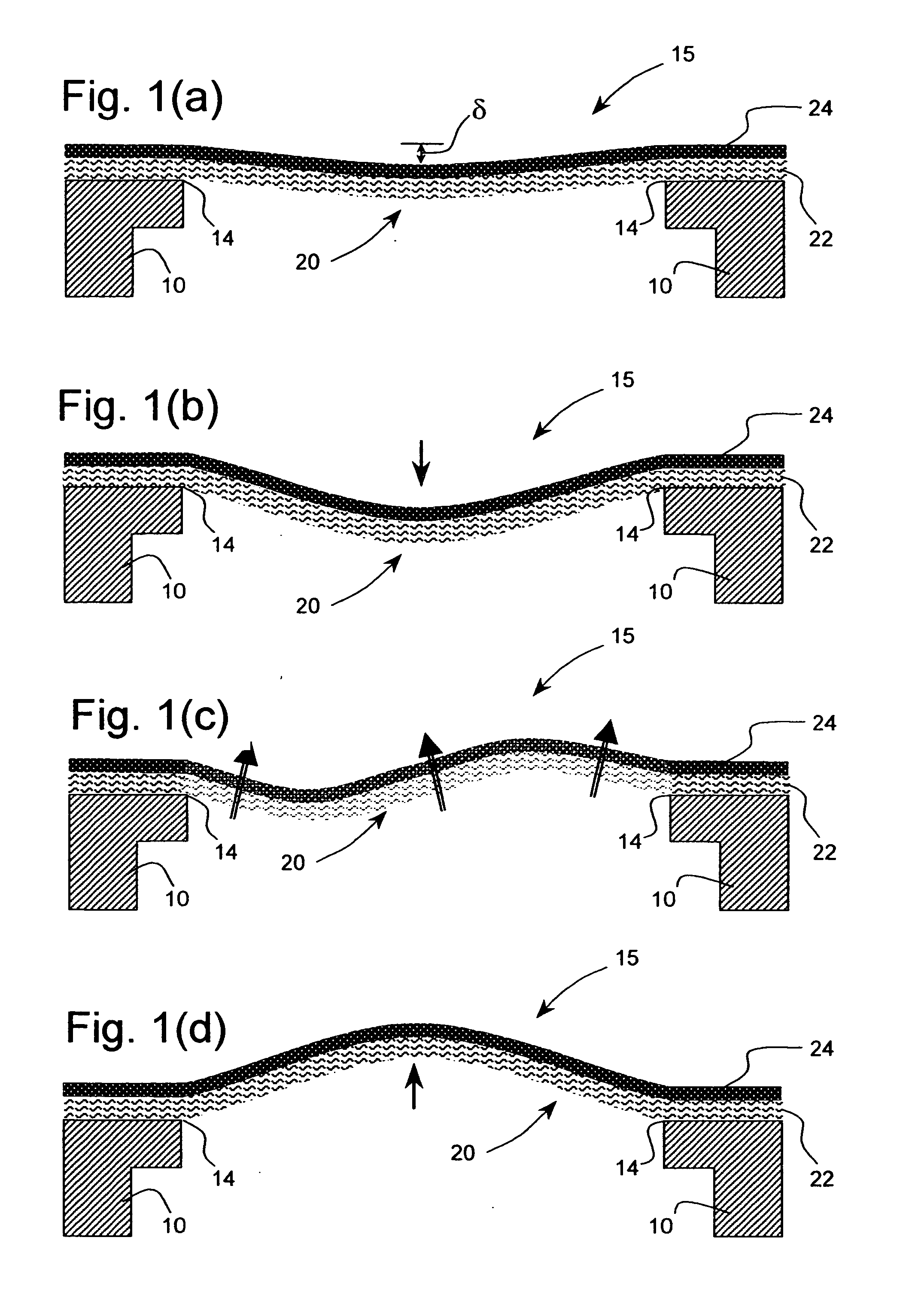
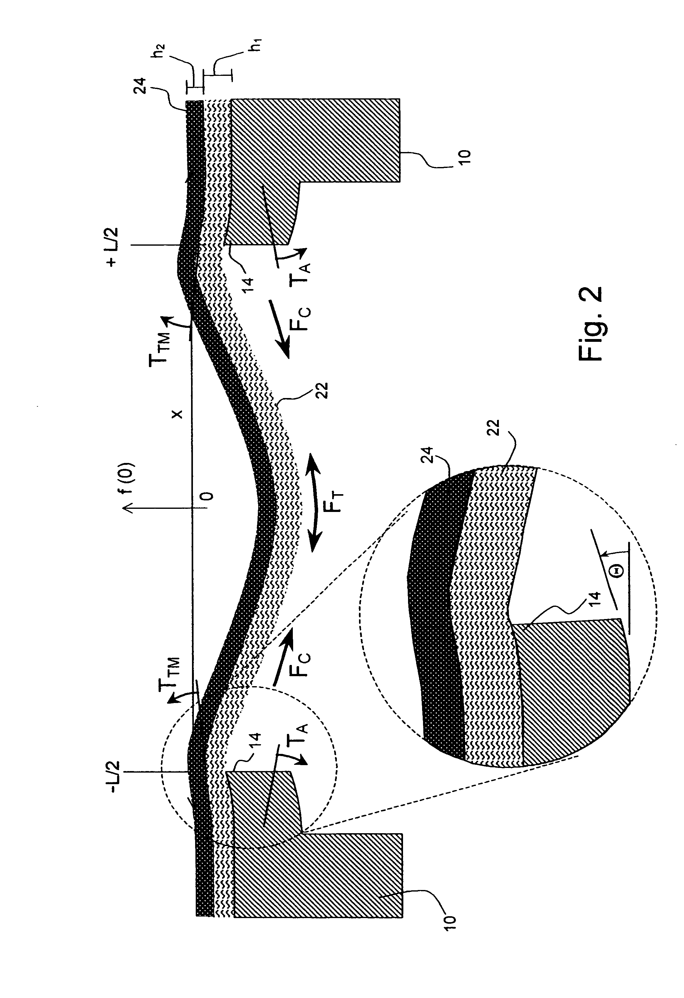
[0052] As described in detail herein below, the present invention provides apparatus for a snap-through thermal actuator, a drop-on-demand liquid emission device, and normally closed and normally open microvalves. The most familiar of such devices are used as printheads in ink jet printing systems. Many other applications are emerging which make use of devices similar to ink jet printheads, however which emit liquids other than inks that need to be finely metered and deposited with high spatial precision. The terms ink jet and liquid drop emitter will be used herein interchangeably. The inventions described below provide drop emitters based on thermo-mechanical actuators having improved drop ejection performance for a wide range of fluid propertie...


PUM


Abstract

A snap-through thermal actuator for a micro-electromechanical device such as a liquid drop emitter or a fluid control microvalve is disclosed. The snap-through actuator is comprised of a base element formed with a depression having opposing anchor edges which define a central plane. A deformable element, attached to the base element at the opposing anchor edges, is constructed as a planar lamination including a first layer of a first material having a low coefficient of thermal expansion and a second layer of a second material having a high coefficient of thermal expansion. The deformable element is formed to have a residual shape bowing outward from the central plane in a first direction away from the second layer. The snap-through thermal actuator further comprises apparatus adapted to apply a heat pulse to the deformable element which causes a sudden rise in the temperature of the deformable element. The deformable element initially bows farther outward in the first direction, then, due to thermomechanical torque's acting at the opposing anchor edges, reverses and snaps through the central plane to bow outward in a second direction toward the second layer, and then relaxes to the residual shape as the temperature decreases. The snap-through thermal actuator is configured with a liquid chamber having a nozzle, a fluid flow port to form a liquid drop emitter or a fluid control microvalve, or to activate an electrical microswitch. Heat pulses are applied to the deformable element by resistive heating or by light energy pulses.

Description

FIELD OF THE INVENTION [0001] The present invention relates generally to micro-electromechanical devices and, more particularly, to micro-electromechanical thermal actuators such as the type used in ink jet devices and other liquid drop emitters. BACKGROUND OF THE INVENTION [0002] Micro-electro mechanical systems (MEMS) are a relatively recent development. Such MEMS are being used as alternatives to conventional electro-mechanical devices as actuators, valves, and positioners. Micro-electromechanical devices are potentially low cost, due to use of microelectronic fabrication techniques. Novel applications are also being discovered due to the small size scale of MEMS devices. Many potential applications of MEMS technology utilize thermal actuation to provide the motion needed in such devices. For example, many actuators, valves and positioners use thermal actuators for movement. In some applications the movement required is pulsed. For example, rapid displacement from a first positio...

Claims


Application Information

Patent Timeline
Patent Type & Authority Applications(United States)
IPC IPC(8): B41J2/14
CPCB41J2002/14346B41J2/14
Inventor CABAL, ANTONIOLEBENS, JOHN A.TRAUERNICHT, DAVID P.ROSS, DAVID S.
Owner EASTMAN KODAK CO
Why Eureka
Try Eureka