Trowel gearbox brake

a gearbox and trowel technology, applied in the direction of gearing, manufacturing tools, ways, etc., can solve the problems of affecting the operation of the trowel, and causing the trowel to spin undetectedly, so as to inhibit or prevent the rotation of the trowel's frame, and hinder the operator's ability to steer

Inactive Publication Date: 2005-05-12
HUSQVARNA AB
View PDF7 Cites 5 Cited by
  • Summary
  • Abstract
  • Description
  • Claims
  • Application Information

AI Technical Summary

Problems solved by technology

For instance, the rotating blades impose substantial torque on the cage that normally is counteracted by the operator through the handle.
If the operator releases the handle while the rotor is being driven, the torque may cause the trowel to spin undesirably.
However, merely shutting down the engine or otherwise ceasing the delivery of drive torque to the trowel's rotor does not necessarily prevent the trowel from spinning because the handle and cage have considerable momentum at the time of shut down.
This slow response to an attempted shut down is undesirable.
Although this device works reasonably well, it exhibits several drawbacks.
In addition, the clutch brake engages automatically only if a mechanical sensor indicates that the trowel is undergoing unacceptable centrifugal forces.
The brake also imposes significant drag on the drive belt, accelerating wear on the drive belt.
Known clutch brakes lack some of the drawbacks of the Stone clutch brake but have drawbacks of their own, rendering them poorly suited for use with a trowel.
This continuous squeezing requirement leads to considerable operator fatigue and also requires that the operator divert a substantial portion of his or her attention to operation of the control lever, hindering his or her ability to adequately steer the trowel.
In addition, as with the Stone system, the range of clutches useful with this type of system is considerably limiting.
The magneto employed as an electrical power source for a typical walk behind trowel is ineffective for the purpose.
Adding additional components to the trowel to upgrade the power supply would add additional cost and weight to the trowel.

Method used


Image

  • Trowel gearbox brake
  • Trowel gearbox brake
  • Trowel gearbox brake

Examples


Embodiment Construction

1. Resume

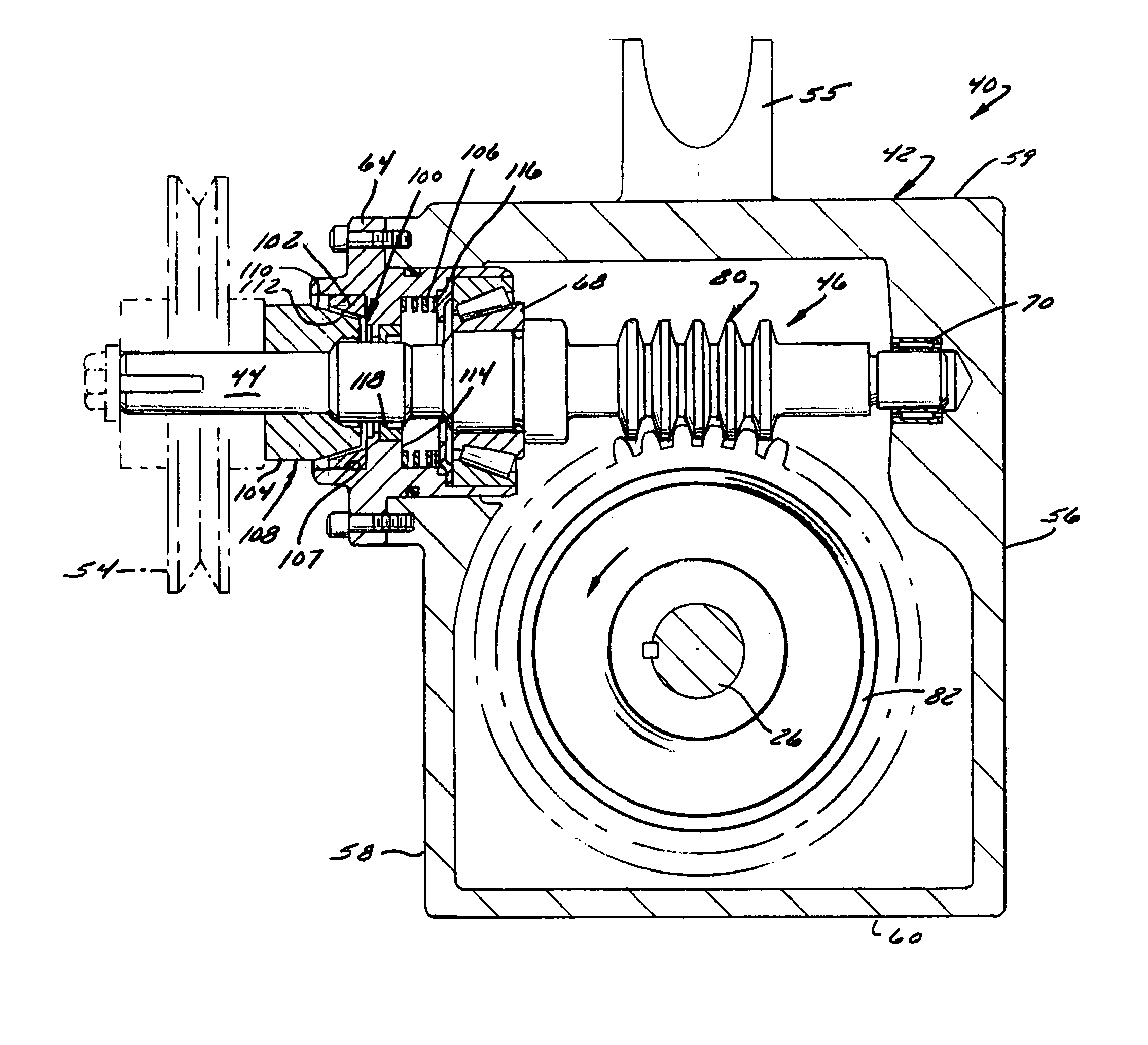
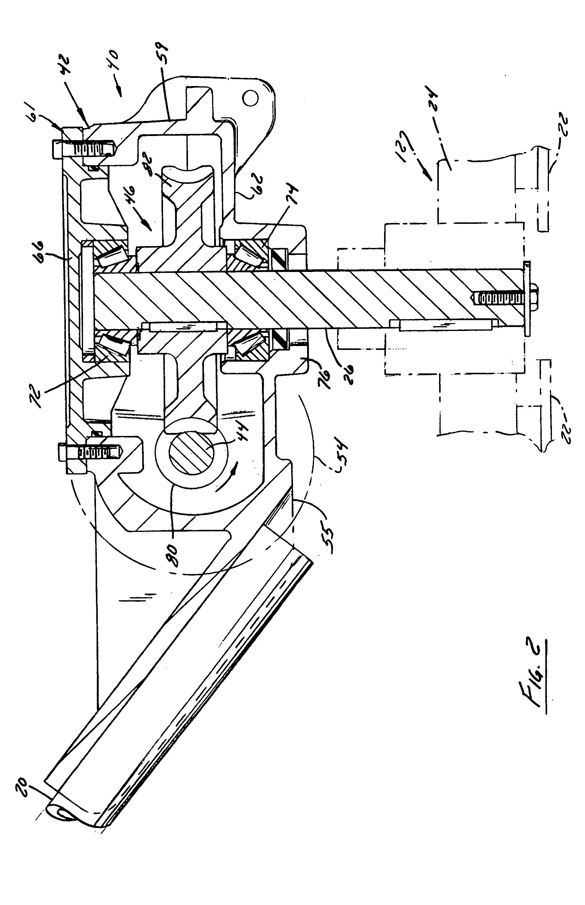
[0022] As indicated above, the invention resides in the automatic braking of an active component of a rotary trowel's drive train in response to the cessation of torque transfer to the rotor from the trowel's prime mover in order to inhibit or prevent undesired rotation of the trowel's frame and handle. Preferably, the brake moves with a component of the drive train that is subject to axial reaction forces upon the delivery of drive torque therethrough. A preferred embodiment of the invention will now be described in conjunction with a walk behind trowel having an internal combustion engine as a prime mover and a brake built into the trowel's gearbox. However, the invention is not so limited. It also potentially applies to ride on trowels and / or to a brake that acts on components of the trowel's drive system other than the gearbox.

2. System Overview

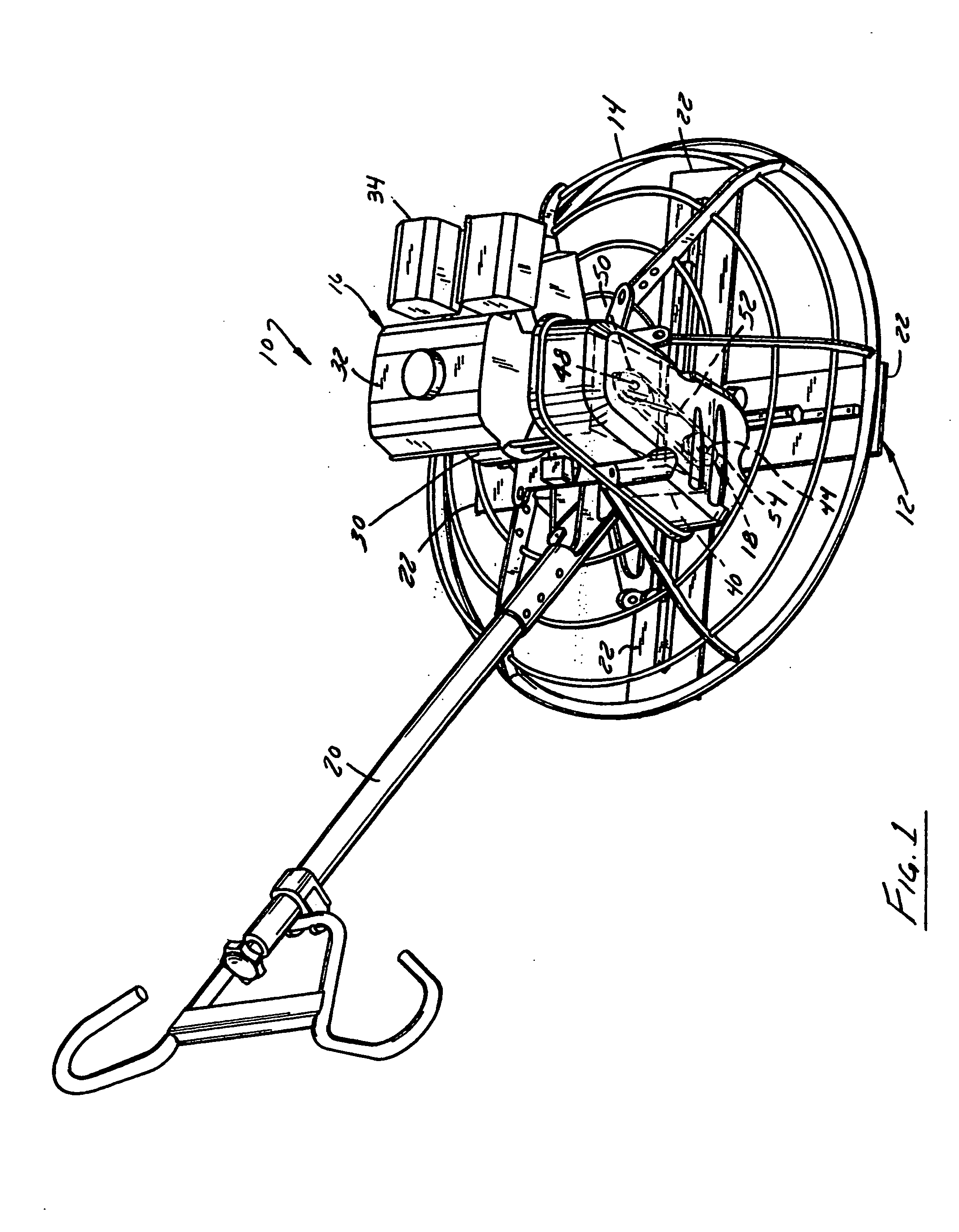
[0023] Referring to FIG. 1, a walk behind trowel 10 is illustrated that incorporates a gearbox brake assembly 100 (FIGS. 3...


PUM

PropertyMeasurementUnit
torqueaaaaaaaaaa
axial reaction forcesaaaaaaaaaa
drive torqueaaaaaaaaaa

Abstract

A brake of a concrete finishing trowel responds automatically to the cessation of drive torque delivery to the rotor to actively brake the trowel's drive train, hence inhibiting or preventing frame rotation. The brake preferably takes advantages of inherent characteristics of an inclined gear, such as a worm of a gearbox, to permit an internal component of the gearbox to shift automatically upon the cessation of drive torque therethrough from a brake released position to a brake engaged position. In the case of a worm gear-based gearbox, the worm is configured such that reaction forces that are normally generated by the delivery of drive torque therethrough shift the worm to release the brake during normal trowel operation. These forces are eliminated in the absence of drive torque transfer, permitting the worm to shift to a brake engaged position.

Description

BACKGROUND OF THE INVENTION [0001] 1. Field of the Invention [0002] The invention relates to concrete finishing trowels and, more particularly, relates to a concrete finishing trowel having a drive train that is braked automatically upon the cessation of drive torque delivery therethrough. The invention additionally relates to an automatically braked gearbox usable with such a trowel and to a method of braking such a gearbox. [0003] 2. Discussion of the Related Art [0004] Walk behind trowels are generally known for the finishing of concrete surfaces. A walk behind trowel generally includes a rotor formed from a plurality of trowel blades that rest on the ground. The rotor is driven by a motor mounted on a frame or “cage” that overlies the rotor. The trowel is controlled by an operator via a handle extending several feet from the cage. The rotating trowel blades provide a very effective machine for finishing mid-size and large concrete slabs. However, walk behind trowels have several...

Claims


Application Information

Patent Timeline
Patent Type & Authority Applications(United States)
IPC IPC(8): B28B1/29B28B11/08E04F21/24F16D55/02F16D65/02F16D65/14F16D67/02F16H1/16F16H61/16
CPCE04F21/24F16H1/16F16D2127/005F16D2065/024E04F21/248
Inventor JENKINS, MICHAELKRUEPKE, GREGORY
Owner HUSQVARNA AB
Why Eureka
Try Eureka