Automated transmission systems

a transmission system and automatic technology, applied in the direction of braking systems, process and machine control, instruments, etc., can solve the problems of unexpected acceleration of the vehicle, loss of engine braking applied in the higher gear, and driver disconcerting,

Active Publication Date: 2006-10-17
SCHAEFFLER TECH AG & CO KG
View PDF16 Cites 5 Cited by
  • Summary
  • Abstract
  • Description
  • Claims
  • Application Information

AI Technical Summary

Benefits of technology

[0004]According to one aspect of the present invention an automated transmission system for a vehicle comprises a multi-ratio gear box connected to an engine by means of a transmission clutch, a transmission brake acting on a component of the transmission between the transmission clutch an the driven wheels of the vehicle, an electronic control unit, means for sensing actuation of the transmission brake and sending a signal indicative thereof to the control unit, means for sensing the engine torque and sending a signal indicative thereof to the control unit, means for sensing the vehicle speed and sending a signal indicative thereof to the control unit, means for sensing whether a gear downshift is requested or in operation and sending a signal indicative thereof to the control unit, and means for sensing whether an operating brake of the vehicle is applied and sending a signal indicative thereof to the control unit; characterized in that the control unit controls operation of the transmission brake to apply a braking torque to the transmission, if the engine torque is negative, the vehicle speed is above a predetermined value, a gear downshift has been requested or is in progress and the operational brakes of the vehicle are not applied.

Problems solved by technology

In such circumstances when the clutch is automatically released in order to permit engagement of a lower gear, engine braking which was applied in the higher gear will be lost, thus allowing the vehicle to speed up.
However, with an automated transmission system, when the system downshifts automatically, without input from the driver, the acceleration of the vehicle will be unexpected and would be disconcerting to the driver.

Method used


Image

  • Automated transmission systems
  • Automated transmission systems
  • Automated transmission systems

Examples


Embodiment Construction

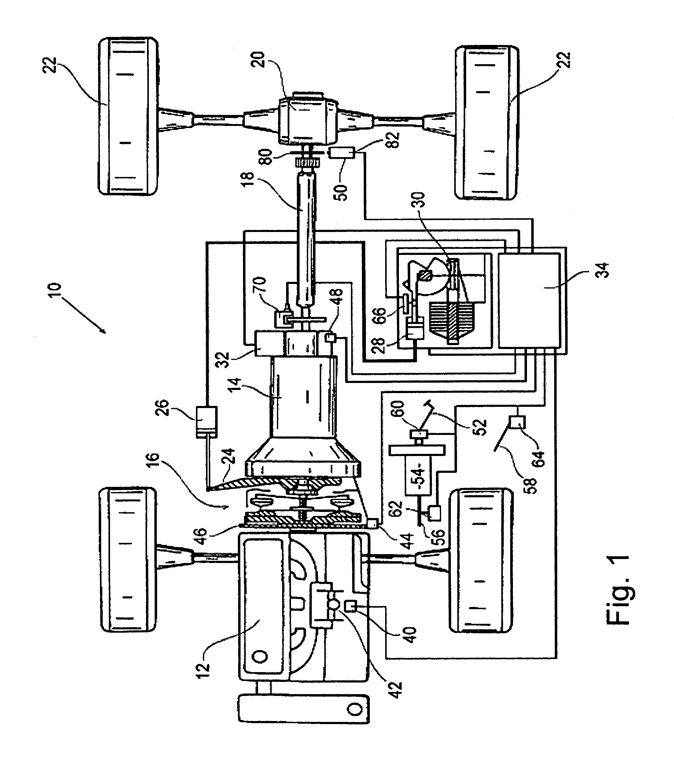
[0017]As illustrated in FIG. 1, a vehicle 10 has an internal combustion engine 12, which is connected to a gearbox 14 via a clutch 16. The gearbox 14 is connected by a drive shaft 18 and rear axle 20 to drive the rear wheels 22 of the vehicle 10.

[0018]The clutch 16 is operated by a release fork 24, which is operated by a hydraulic slave cylinder 26, under the control of a master cylinder 28, driven by an electric motor 30. Alternatively the clutch slave cylinder may be selectively connected to a source of hydraulic fluid under pressure or the drain via control valve means. According to alternative embodiments, the clutch release lever may be operated by pneumatic means or electromechanical means, the electromechanical means being connected to the release lever, either directly or by cable means.

[0019]The gearbox 14 is provided with gear engagement means 32, for example as disclosed in WO 02 / 066870, the disclosure content of which is incorporated into the disclosure content of the pr...


PUM


Abstract

An automated transmission system includes a transmission brake which is used to apply a braking torque to the transmission, while the engine torque is negative and a transmission clutch is disengaged to effect a gear downshift, in order to avoid acceleration of the vehicle when the clutch is released and abrupt deceleration of the vehicle upon completion of the gear downshift.

Description

CROSS-REFERENCE TO RELATED APPLICATION[0001]This patent claims priority of United Kingdom Patent Application No. 0301171.5, filed Jan. 18, 2003, which application is incorporated herein by reference.BACKGROUND OF THE INVENTION[0002]The present invention relates to automated transmission systems and in particular to automated transmission systems in which an automatically operated transmission clutch is provided between a vehicle engine and a multi-ratio gear box.[0003]The invention particularly relates to the control of such systems when gear downshifting on an incline, in order to provide engine braking of the vehicle. In such circumstances when the clutch is automatically released in order to permit engagement of a lower gear, engine braking which was applied in the higher gear will be lost, thus allowing the vehicle to speed up. In similar circumstances with a manual transmission, this would be expected and the driver can take appropriate action to mitigate the effect. However, w...

Claims


Application Information

Patent Timeline
Patent Type & Authority Patents(United States)
IPC IPC(8): G01P13/04G01P3/54G06F17/00F16H61/02B60T1/06B60W10/10B60W10/18B60W30/18F16H61/04F16H61/22
CPCB60T1/06B60W10/11B60W10/18B60W30/18109B60W30/18136F16H61/04F16H61/21Y10T477/619F16H61/22F16H2061/0425F16H2312/04F16H2061/0496Y10T477/6388B60W30/00F16H61/0202G06F1/187
Inventor BATES, IAN RICHARD JOSEPHPOLLAK, BURKHARDSONG, IN HOPARK, YOUNGKEUNRIEGER, CHRISTIAN
Owner SCHAEFFLER TECH AG & CO KG
Why Eureka
Try Eureka