Vehicle Door Comprising a Deceleration Function

a technology of vehicle doors and functions, applied in the direction of doors, wing accessories, transportation and packaging, etc., can solve the problems of inability to prevent damage to doors or obstacles, etc., and achieve the effect of preventing mechanical loading of hinges and high quality

Inactive Publication Date: 2009-01-08
DAIMLER AG
View PDF13 Cites 53 Cited by
  • Summary
  • Abstract
  • Description
  • Claims
  • Application Information

AI Technical Summary

Benefits of technology

[0003]Doors with a fixed stop have a wide opening angle so that there is no collision protection in tight parking spaces / garages. Provided that a suitable sensor system can be used to detect an obstacle in the opening region of the door, it is possible to prevent a collision by means of a variable stop.
[0010]As a result, the vehicle door is advantageously braked aperiodically before the mechanical end stops or an obstacle is reached, as a result of which damage, severe shaking, noise and vibrations are avoided. This provides a high quality impression of the vehicle and favors the service life of the accessory parts, in particular of electrical and electronic circuits which are arranged in the vehicle door, and prevents mechanical loading of the hinges. When the vehicle door opens, it is braked in such a way that it comes to rest just before the mechanical stop or before a detected obstacle and is held in a latched position. When the vehicle door closes, its speed is reduced in such a way that the vehicle door reliably engages in the lock but does not impact against the vehicle with an unnecessarily large amount of force.

Problems solved by technology

If vehicle doors are opened carelessly, it is easy for collisions with obstacles to occur, resulting in damage to the door or to the obstacle.
With current latching mechanisms, which generally have only one or two permanently predefined latching positions for the door, this is not possible.

Method used


Image

  • Vehicle Door Comprising a Deceleration Function
  • Vehicle Door Comprising a Deceleration Function
  • Vehicle Door Comprising a Deceleration Function

Examples


Embodiment Construction

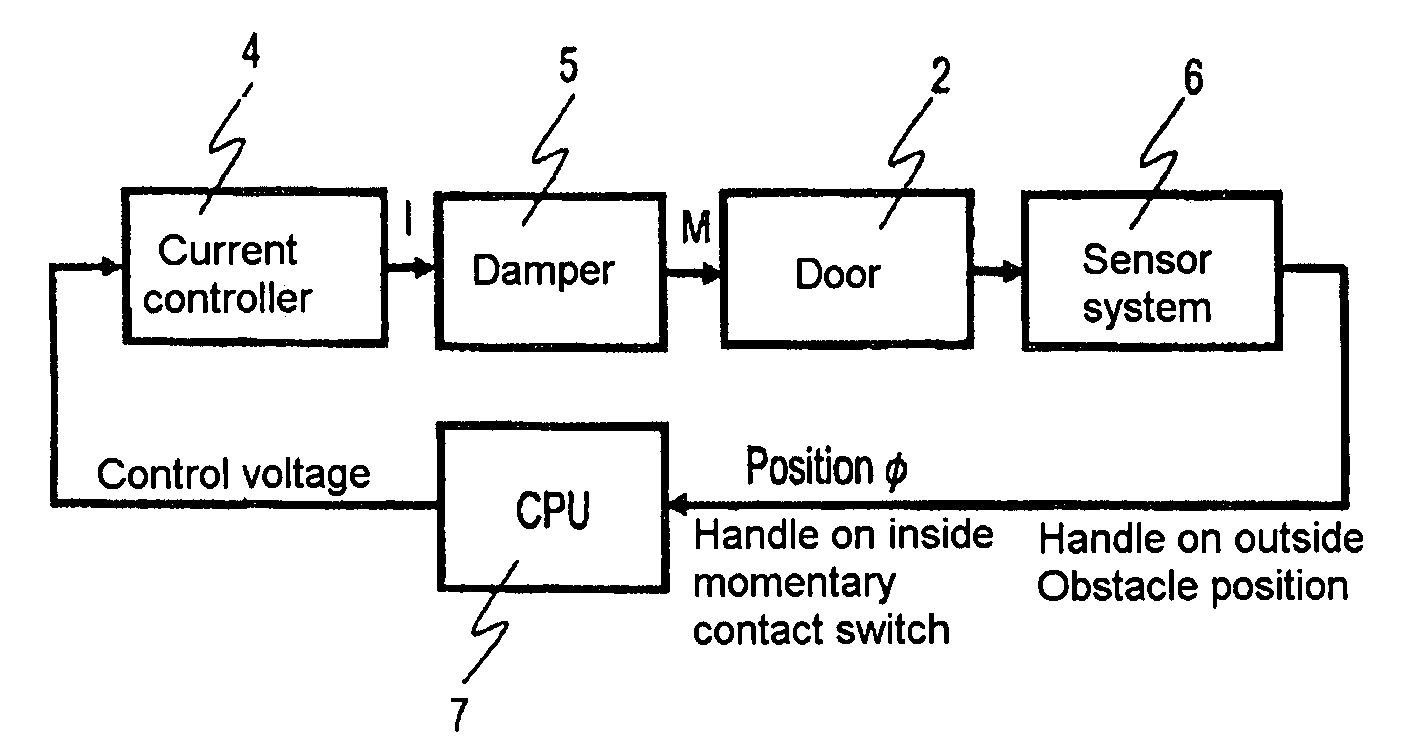
[0029]As is apparent from FIG. 1, a vehicle door 2 according to the invention comprises a sensor system 6 for sensing the door movement, an evaluation and control unit 7 for evaluating the sensed door movement and for actuating a damper 5 by means of an actuator 4, with the damper influencing the movement of the vehicle door 2 by means of a set torque M. The evaluation and control unit 7 outputs, for example, a control voltage U which is converted by the actuator 4 into a current I. In addition to the sensing of the door movement, the sensor system 6 can also comprise sensors for monitoring an internal door handle or external door handle or for detecting obstacles in the opening area of the vehicle door 2.

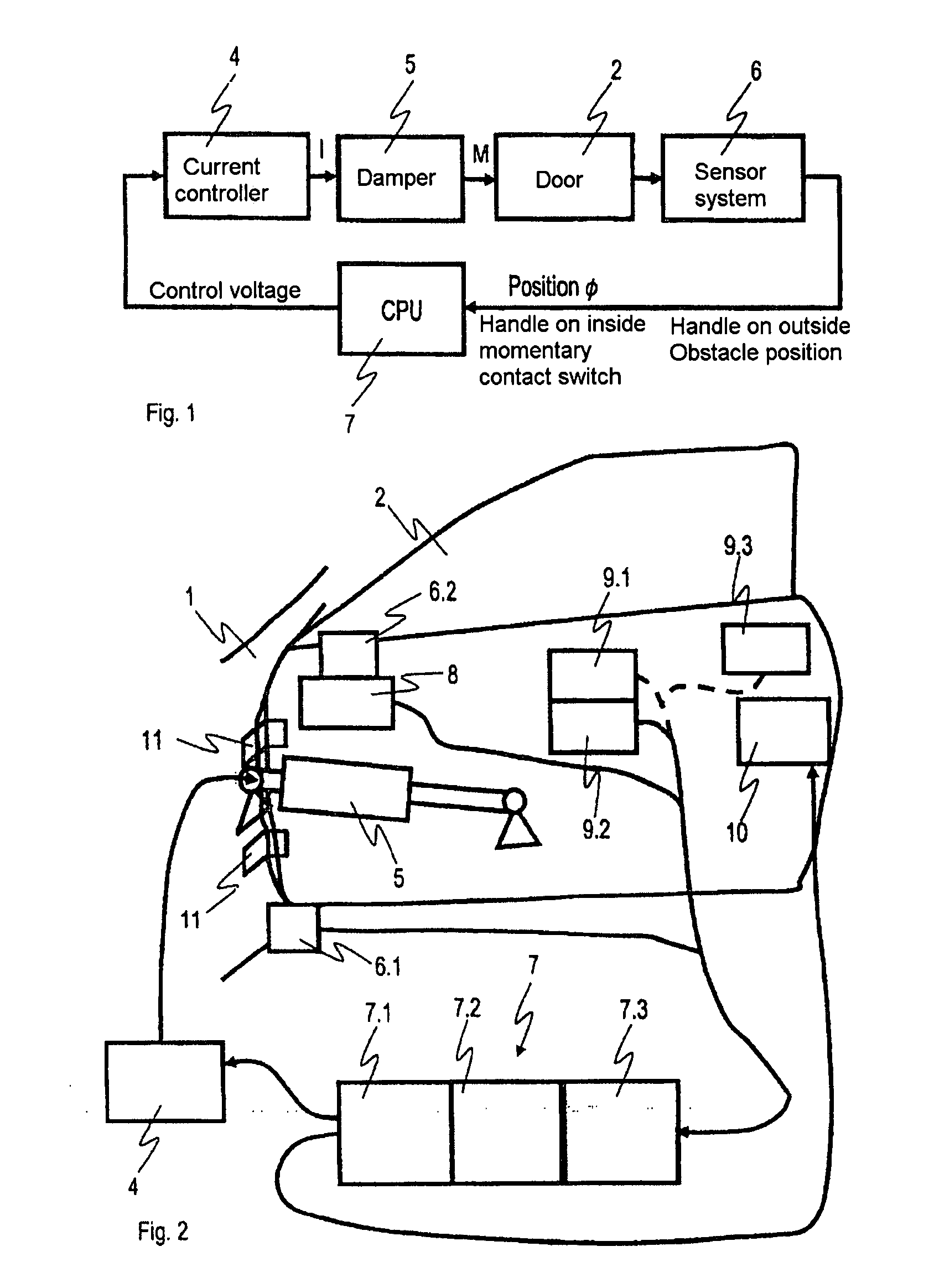
[0030]FIG. 2 shows a more detailed block circuit diagram of the vehicle door 2 with a braking function for a vehicle 1. As is apparent from FIG. 2, the vehicle door 2 comprises hinges 11, the damper 5 with the actuator 4 which is embodied as a current controller and which is actuat...


PUM


Abstract

The invention relates to a vehicle door comprising a braking function before a detected obstacle (3) and for damping the final position, which decelerates the movement of the vehicle door (2) by applying a braking torque, wherein an evaluation and control unit (7) determines the braking torque by evaluating an instantaneous door movement, which is sensed by a sensor system (6), or a sensed obstacle and actuates the damper (5) correspondingly. According to the invention, the braking function decelerates the vehicle door (2) aperiodically taking into account interference torques, wherein the evaluation and control unit (7) determines the braking torque for the braking function, in that during an opening process the vehicle door (2) reaches a target position with a speed with the value zero, and during a closing process reaches an end position (φ0) with a predefined target speed, wherein the target position corresponds to a predefined maximum opening angle (φmax) or a virtual stop which is determined by an obstacle (3) which is detected by the sensor system.

Description

BACKGROUND AND SUMMARY OF THE INVENTION[0001]This invention relates to a vehicle door having a braking function.[0002]If vehicle doors are opened carelessly, it is easy for collisions with obstacles to occur, resulting in damage to the door or to the obstacle. A frequently occurring scenario is people getting out of the vehicle in tight parking spaces or garages. In this context, it is often necessary to open the door as far as possible against the neighboring vehicle or the walls for it to be possible at all to get out of the vehicle. This requires a latching mechanism with variable latching which allows the door to be positioned precisely. With current latching mechanisms, which generally have only one or two permanently predefined latching positions for the door, this is not possible. The door often opens too wide or does not remain opened.[0003]Doors with a fixed stop have a wide opening angle so that there is no collision protection in tight parking spaces / garages. Provided tha...

Claims


Application Information

Patent Timeline
Patent Type & Authority Applications(United States)
IPC IPC(8): E05F15/20B60J5/04
CPCE05B2047/0033E05C17/006E05C17/30E05F5/025E05Y2201/21E05F2015/483E05Y2900/531E05Y2201/25E05Y2201/254E05F15/43E05Y2400/532
Inventor KERN, SIMONMAAS, JUERGENSEILER, BERND
Owner DAIMLER AG
Why Eureka
Try Eureka