Transmission brake disengagement switch and method of operation

a technology of disengagement switch and transmission brake, which is applied in the direction of brake action initiation, gearing control, braking system, etc., can solve the problem of the amount of delay of a conventional switch

Active Publication Date: 2015-02-10
PENNER ERNEST PETER
View PDF4 Cites 7 Cited by
  • Summary
  • Abstract
  • Description
  • Claims
  • Application Information

AI Technical Summary

Benefits of technology

[0050]According to yet another aspect of the invention there is provided a transmission brake control switch for a vehicle, comprising a switch device operable to open and close a conductive path between transmission brake connection points at which the switch is connectable in a control circuit of a transmission brake in a manner such that opening and closing of the conductive path switches the transmission brake between on and off states, the switch comprising a plunger supported for movement along an axis thereof between a normal position into which it is biased, a first depressed position in which the transmission brake is continuously engaged in an on state, a second depressed position further from the normal position than the first depressed position and in which the transmission brake is at least intermittently disengaged from the on state, and a third depressed position further from the normal position than the second depressed position and in which the transmission brake is continuously engaged in the on state, whereby the switch is operable to hold the vehicle stationary through continuous engagement of the transmission brake when initially depressed to the first depressed position, allow creeping of the vehicle through at least intermittent disengagement of the transmission brake upon further depression to the second depressed position, and re-establish the continuous engagement of the transmission brake upon still further depression to the third depressed position to again hold the vehicle stationary.

Problems solved by technology

Unfortunately the setting of the amount of delay of a conventional switch has to be completed prior to entering the staging positions as the driver does not have the time available to make a mechanical adjustment.

Method used


Image

  • Transmission brake disengagement switch and method of operation
  • Transmission brake disengagement switch and method of operation
  • Transmission brake disengagement switch and method of operation

Examples


first embodiment

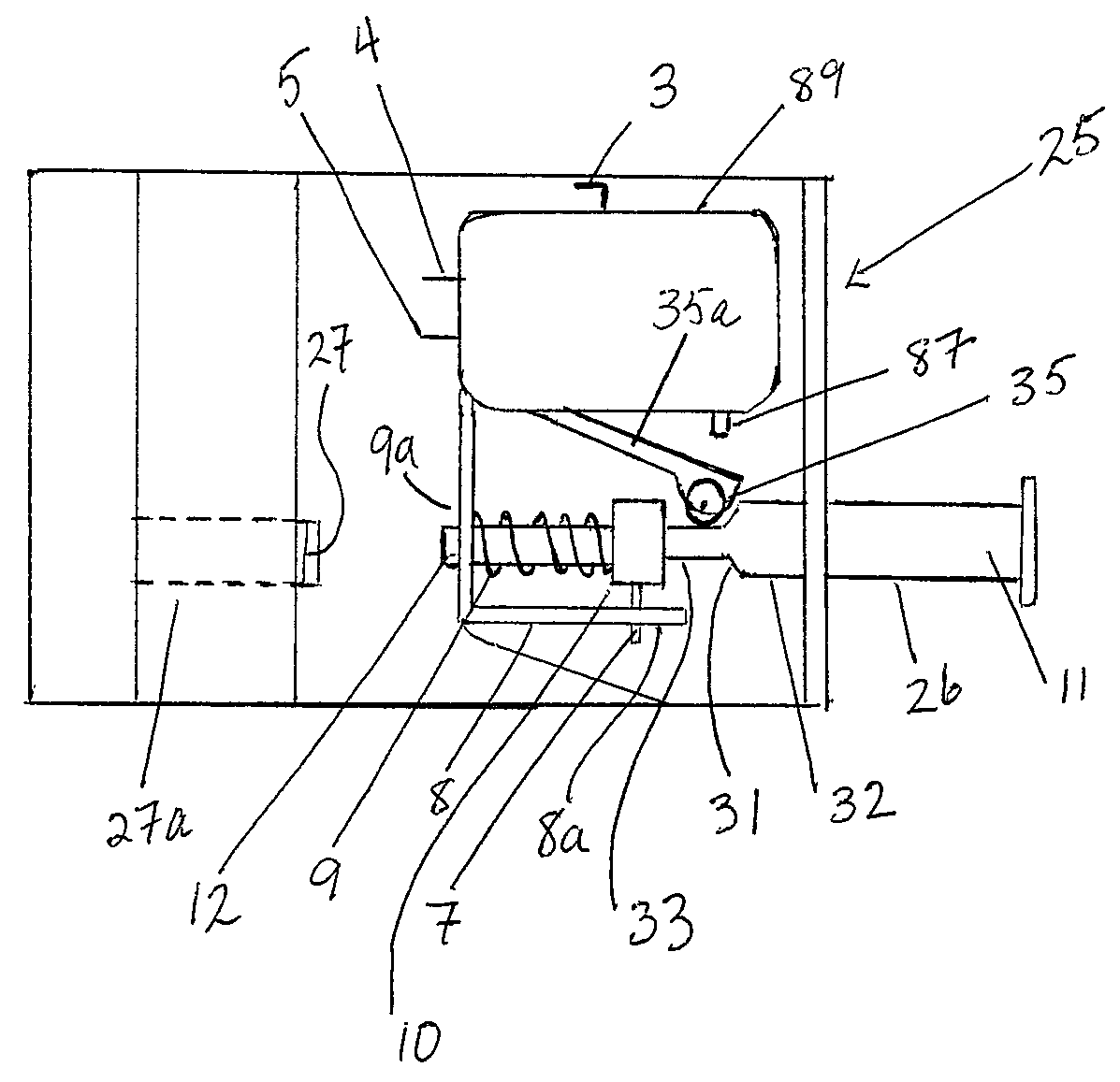
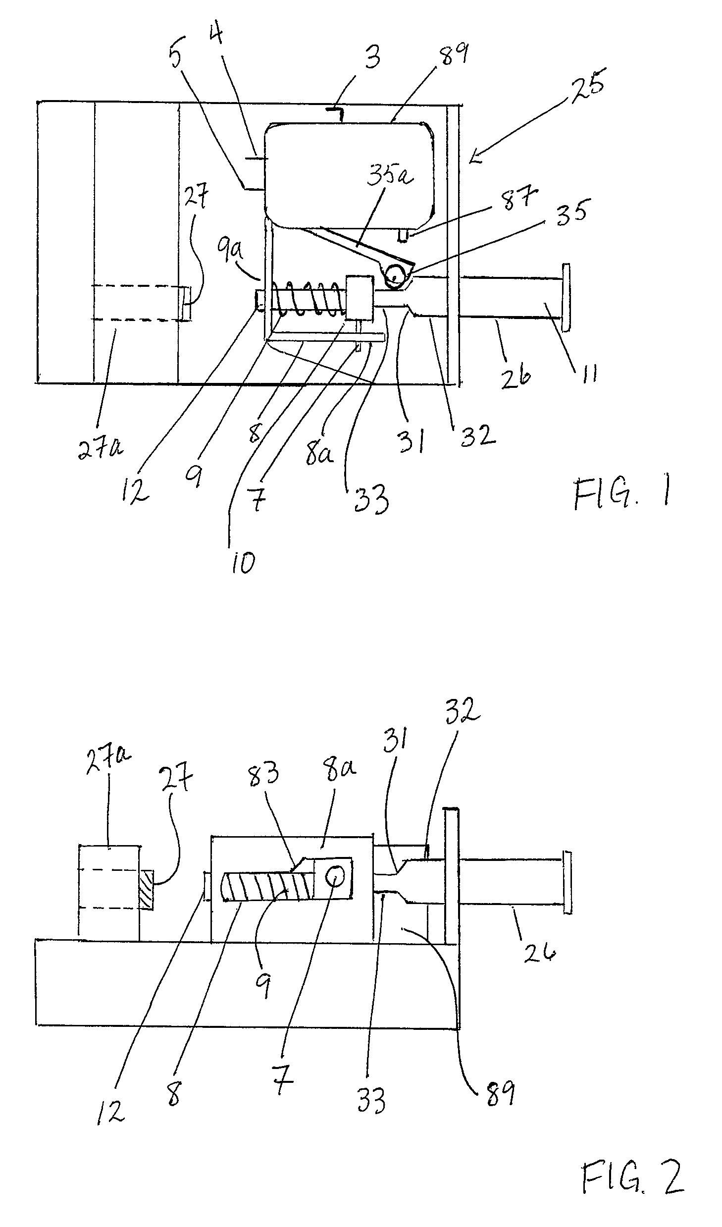
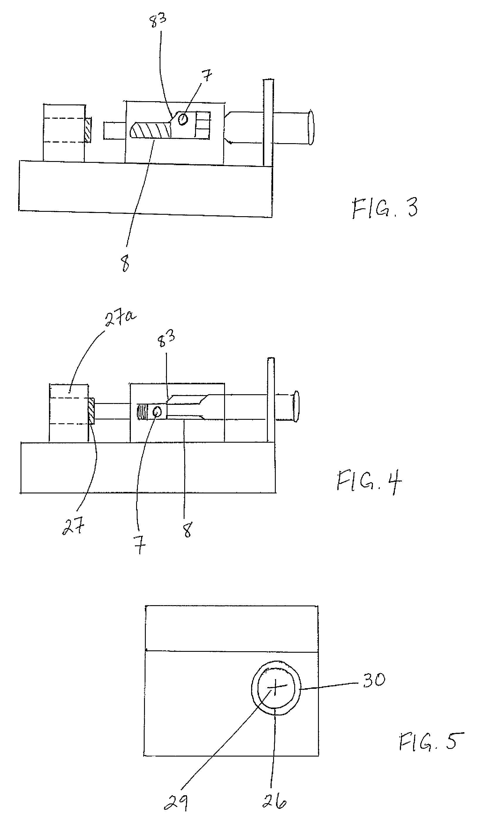
[0085]As in the first embodiment, the driver has the option of depressing the plunger even further before release of the same in order to move the pin 7 past the final cam position 83 toward the end of the guide slot, thereby increasing the delay time from manual release of the plunger to the disengagement of the transmission brake.

[0086]Of note, in order to maintain a clean on-off transition of the transmissions brake through movement of the roller 35 from flat 39 to flat 33, the detent 37 spans less than 360 degrees of the plunger 266 circumference or outer diameter (OD) so as to be engaged by roller 35 in the angular position of the plunger corresponding to positioning of pin 7 at cam portion 84, but not be engaged by roller in the angular position of the plunger corresponding to positioning of pin 7 at cam portion 83 and beyond. Thereby the detent 37 would be avoided on release due to rotation of plunger 266 on axis 29 dictated by alignment pin 7 and guide slot 87. Also of note ...

second embodiment

[0088]Another example of use of the second embodiment plunger is described as follows with reference to FIGS. 6 to 8 and 10. FIG. 10 illustrates a control circuit similar to that of FIG. 9, but adding a double pole switch 100 having a double throw pole 100a inserted between the microswitch 89 and the front wheel brake-locking solenoid 90 in order to control operation of a pulsed-brake control 102 of the circuit, which is configured for operation of the transmission brake in a pulsing manner. A pulsing relay 104 has its contact terminals wired between one contact of the double throw pole 100a of the switch 100 and a third normally open momentary switch 106. The other terminal on the same pole of the third normally open momentary switch 106 is wired to the transmission brake solenoid. The other contact of the double throw pole 100a of the switch 100 is wired to the front wheel brake-locking solenoid 90, whereby the position of the double throw switch 100 determines whether pin 5 of th...


PUM


Abstract

Controls for a transmission brake include a switch that employs resistance to motion of an axially movable plunger in order to provide tactile feedback to the operator as to the current position of the plunger, thus reflecting a particular state of the switch. In a fully depressed position of the plunger, the transmission brake is on. Shortly before this position is reached, resistance is encountered at an intermediate position at which the transmission brake is already engaged, thereby giving the user of the option of depressing the plunger further in order to provide a longer travel time of plunger back to its normal spring-biased position in which the brake is disengaged. Some embodiments activate other brake control components at partially depressed plunger positions preceding the intermediate position, whereby controlled creeping of the vehicle can be accomplished before the transmission brake is returned to a continuously engaged state.

Description

CROSS REFERENCE TO RELATED APPLICATIONS[0001]This application claims benefit under 35 U.S.C. 119(e) of U.S. Provisional Patent Application Ser. No. 61 / 526,846, filed Aug. 24, 2011.FIELD OF THE INVENTION[0002]The present invention relates to a transmission brake disengagement switch for mounting on a drag race car and more particularly, to a method of activating and deactivating a transmission brake of a drag race car and a transmission brake disengagement apparatus having a mechanical actuation switch for providing an electrical signal to effect the disengagement of an electrically activated transmission brake of a drag race car.BACKGROUND OF THE INVENTION[0003]In the profession of drag racing, drivers strive to cover a fixed distance in a preselected time and the difference between winning and losing a race is often measured in thousandths of a second. Accordingly, the nature of a drag race places importance on the consistency of operation of the mechanisms of the car and the consi...

Claims


Application Information

Patent Timeline
Patent Type & Authority Patents(United States)
IPC IPC(8): B60T7/08F16H63/34F16D63/00
CPCF16D63/00B60T1/062B60T7/042B60T7/085
Inventor PENNER, ERNEST PETER
Owner PENNER ERNEST PETER
Why Eureka
Try Eureka