System for manufacturing an optical lens

a manufacturing system and optical lens technology, applied in the field of manufacturing optical lenses, can solve the problems of reducing the optical performance of the eye, blurring vision, and limited correction of blurred vision by fitting patients with lenses

Active Publication Date: 2005-05-19
ESSILOR INT CIE GEN DOPTIQUE +1
View PDF9 Cites 90 Cited by
  • Summary
  • Abstract
  • Description
  • Claims
  • Application Information

AI Technical Summary

Benefits of technology

[0006] The system, method, and devices of the invention each have several aspects, no single one of which is solely responsible for its desirable attributes. Without limiting the scope of this invention as expressed by the claims which follow, its more prominent features will now be discussed briefly. After considering this discussion, and particularly after reading the section entitled “Detailed Description of Embodiments” one will understand how the features of this invention provide advantages that include convenient and economical methods of manufacturing optical lens and lens blanks.

Problems solved by technology

The human eye, namely the cornea and lens, can exhibit a variety of optical aberrations that diminish the optical performance of the eye, resulting in blurred vision.
The correction of blurred vision by fitting patients with lenses has typically been limited to the correction of low order aberrations only, such as defocus and astigmatism.
Traditionally, high order aberrations, e.g. those describable with Zernike polynomials of the third order or higher, could not be corrected using lenses.
In addition, due to lens manufacturing limitations and expenses, defocus and astigmatism are typically only corrected in discrete steps, with any correction being made to the nearest one quarter (0.25) diopter.
Unfortunately, the resolution of one quarter (0.25) diopter results in incomplete vision correction.

Method used


Image

  • System for manufacturing an optical lens
  • System for manufacturing an optical lens
  • System for manufacturing an optical lens

Examples


Embodiment Construction

” one will understand how the features of this invention provide advantages that include convenient and economical methods of manufacturing optical lens and lens blanks.

[0007] One embodiment is a system for customizing vision correction. The system includes a measurement system configured to measure patient's vision parameters and to create measured optical aberration data. The system further includes a calculation system configured to receive the measured vision parameters and optical aberration data and to determine a lens definition based on the vision parameters and measured optical aberration data. The system further includes a fabrication system configured to produce a correcting lens based on the lens definition wherein the lens definition comprises a correction of at least one high order aberration.

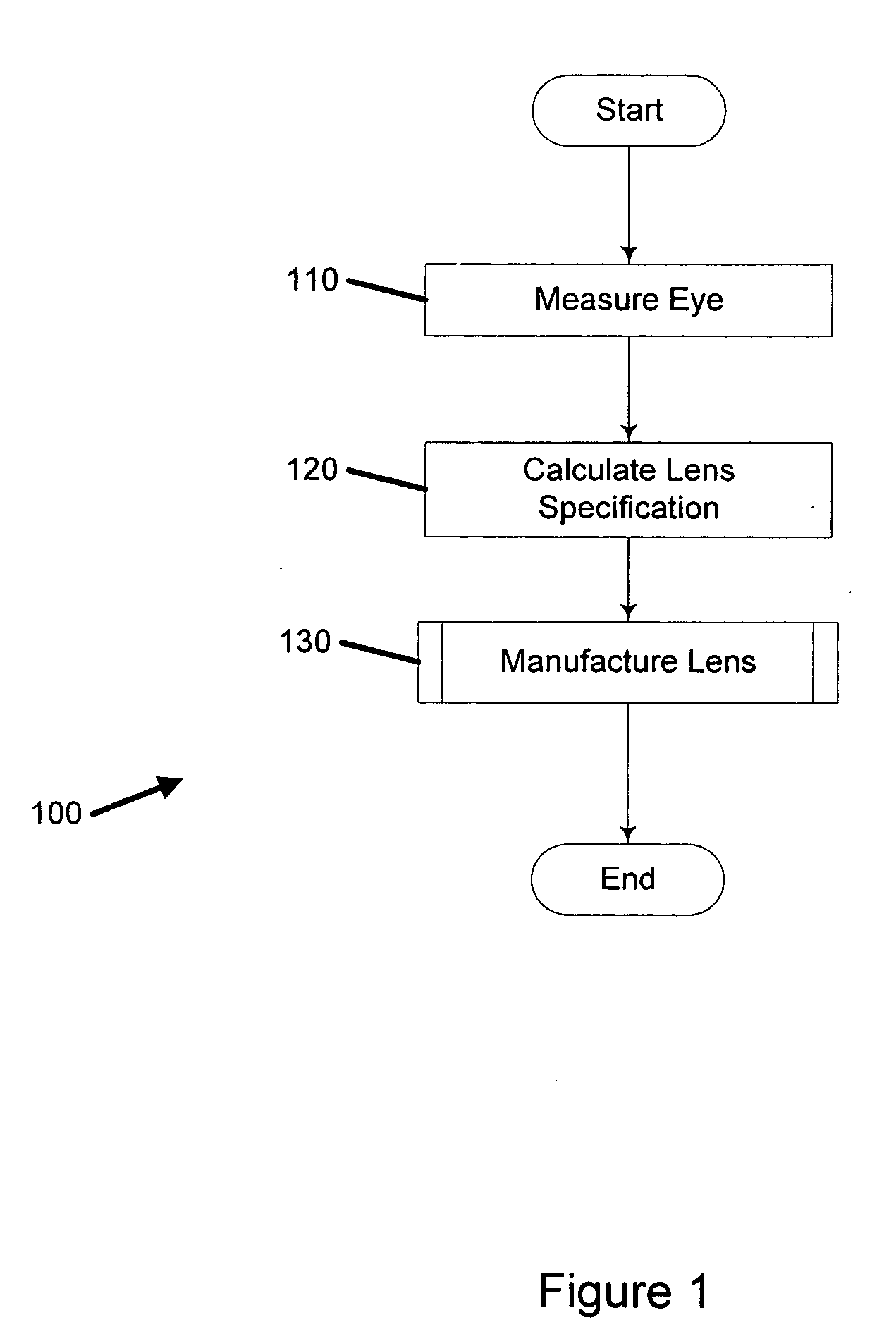
[0008] Another embodiment is a method of customizing vision correction. The method includes measuring optical aberration data of a patient's eye. The method further includes calc...


PUM

PropertyMeasurementUnit
thicknessaaaaaaaaaa
thickaaaaaaaaaa
temperatureaaaaaaaaaa

Abstract

A system for manufacturing an optical lens that is configured to correct optical aberrations, including, e.g., high order aberrations such as described by Zernike polynomials. The system can include a measurement system configured to measure optical aberrations in a patient's eye and to create measured optical aberration data. A calculation system is configured to receive the measured optical aberration data and to determine a lens definition based on the measured optical aberration data. A fabrication system is configured to produce a correcting lens based on the lens definition.

Description

RELATED APPLICATIONS [0001] This application claims the benefit of, and incorporates by reference, U.S. Provisional Application No. 60 / 520,065 filed Nov. 14, 2003. This application also claims the benefit of, and incorporates by reference, U.S. Provisional Application No. 60 / 546,378, filed on Feb. 20, 2004.BACKGROUND OF THE INVENTION [0002] 1. Field of the Invention [0003] The present invention relates to systems and methods relating to manufacturing optical lenses for correcting aberrations of optical systems such as the human eye. [0004] 2. Description of the Related Art [0005] The human eye, namely the cornea and lens, can exhibit a variety of optical aberrations that diminish the optical performance of the eye, resulting in blurred vision. The correction of blurred vision by fitting patients with lenses has typically been limited to the correction of low order aberrations only, such as defocus and astigmatism. Traditionally, high order aberrations, e.g. those describable with Ze...

Claims


Application Information

Patent Timeline
Patent Type & Authority Applications(United States)
IPC IPC(8): B24B13/00B29D11/00G02C13/00
CPCB24B13/00G02C13/003B29D11/00461B29D11/00355B29D11/00442
Inventor WARDEN, LAURENCEDREHER, ANDREAS W.FERRO, JOHNJETHMALANI, JAGDISH M.LAI, SHUI T.
Owner ESSILOR INT CIE GEN DOPTIQUE
Why Eureka
Try Eureka