Switching system with distributed switching fabric
What is AI technical title?
AI technical title is built by PatSnap AI team. It summarizes the technical point description of the patent document.
a technology of switching fabric and switching system, applied in the field of network switches, can solve the problems of overly expensive solution, failure of any given switch, and failure to destroy the integrity of the entire switching system, and the need for redundant systems to be engaged
Inactive Publication Date: 2005-05-19
RAPTOR NETWORKS TECH
View PDF13 Cites 69 Cited by
Summary
Abstract
Description
Claims
Application Information
AI Technical Summary
This helps you quickly interpret patents by identifying the three key elements:
Problems solved by technology
Method used
Benefits of technology
Benefits of technology
[0013] The ingress and egress elements preferably support Ethernet or other protocol providing connectionless media with a stateful connection. At least some of ...
Problems solved by technology
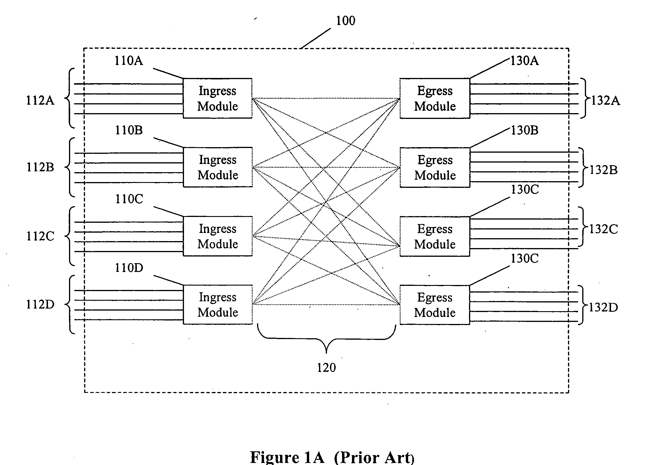
One problem with simple embodiments of the prior art design of FIG. 1 is that failure of any given switch destroys integrity of the entire switching system.
That solution, however, is overly expensive because an entire backup must be deployed for each working system.
The solution is also problematic in that the redundant system must be engaged upon failure of substantially any component within the working system.
But that solution is problematic because all the components are situated locally to one another.
A fire, earthquake or other catastrophe will still terminally disrupt the functionality of the entire system.
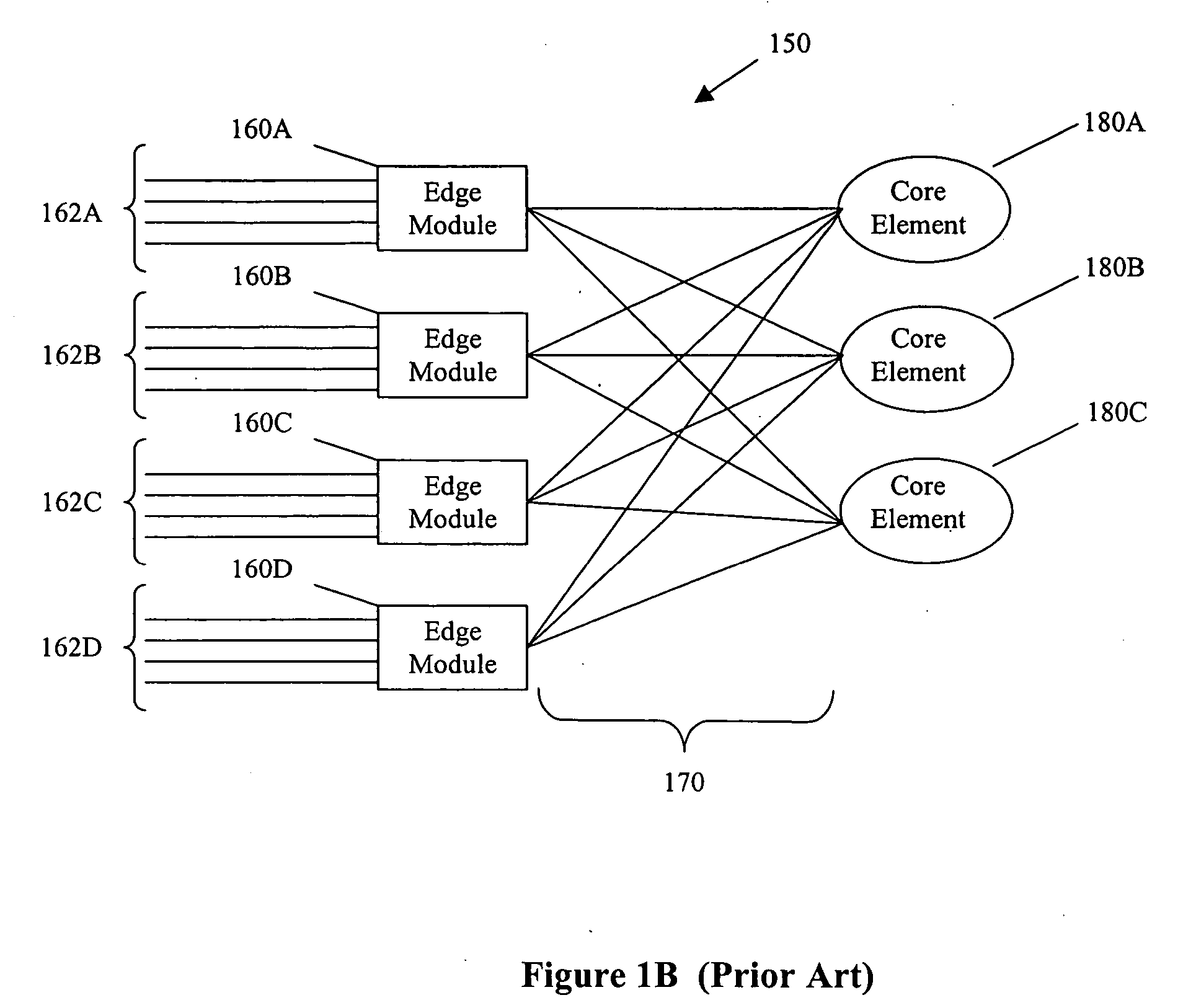
Despite numerous potential advantages, Beshai's solution in the '546 patent has significant drawbacks.
A second drawback is that the optical core is contemplated to be entirely passive.
A third, related disadvantage, is that Beshai's concept only supports a single channel from one module to another.
All of those deficiencies reduce functionality.
Method used
Image
Click on the blue label to locate the original text in one second.
Reading with bidirectional positioning of images and text.
Examples
Embodiment Construction
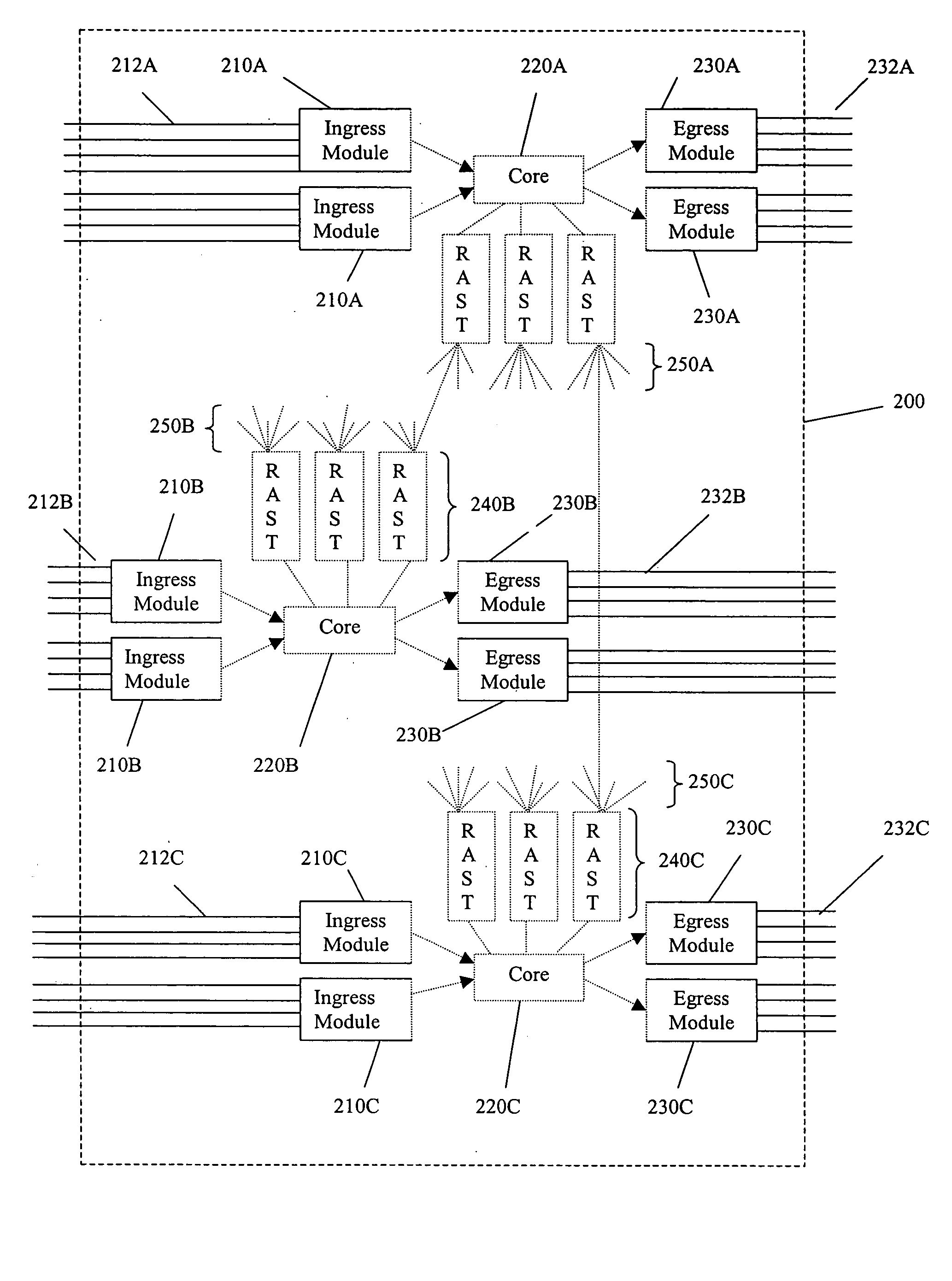
[0025] In FIG. 2 a switching system 200 generally includes ingress elements 210A-C, egress elements 230A-C, core switching elements 220A-C and connector elements 240A-C. The ingress elements encapsulate incoming packets with a routing header (see FIG. 3), and perform initial switching. The encapsulated packets then enter the core elements for further switching. The intermediate elements facilitate communication between core elements. The egress elements remove the header, and deliver the packets to a sink or final destination.
[0026] Those skilled in the art will appreciate that switching (encapsulation) header must, at a bare minimum, include at least a destination element address. In preferred embodiments the header also includes destination port ID, and where elements are clustered and optional destination cluster ID. Also optional are fields for source cluster, source element, and source port IDs. As used herein an “ID” is something that is the same as, or can be resolved into a...
PUM
Abstract
A switch encapsulates incoming information using a header, and removes the header upon egress. The header is used by both distributed ingress nodes and within a distributed core to facilitate switching. The ingress and egress elements preferably support Ethernet or other protocol providing connectionless media with a stateful connection. Preferred switches include management protocols for discovering which elements are connected, for constructing appropriate connection tables, for designating a master element, and for resolving failures and off-line conditions among the switches. Secure data protocol (SDP), port to port (PTP) protocol, and active / active protection service (AAPS) are all preferably implemented. Systems and methods contemplated herein can advantageously use Strict Ring Topology (SRT), and conf configure the topology automatically. Components of a distributed switching fabric can be geographically separated by at least one kilometer, and in some cases by over 150 kilometers.
Description
[0001] This application claims priority to provisional application No. 60 / 511,145 filed Oct. 14, 2003; provisional application No. 60 / 511,144 filed Oct. 14, 2003; provisional application No. 60 / 511,143, filed Oct. 14, 2003; provisional application No. 60 / 511,142 filed Oct. 14, 2003; provisional application No. 60 / 511,141 filed Oct. 14, 2003; provisional application No. 60 / 511,140 filed Oct. 14, 2003; provisional application No. 60 / 511,139 filed Oct. 14, 2003; provisional application No. 60 / 511,138 filed Oct. 14, 2003; provisional application No. 60 / 511,021 filed Sep. 14, 2003; and provisional application No. 60 / 563,262 filed Apr. 16, 2004, all of which are incorporated herein by reference in their entirety.FIELD OF THE INVENTION [0002] The field of the invention is network switches. BACKGROUND [0003] Modern computer networks typically communicate using discrete packets or frames of data according to predefined protocols. There are multiple such standards, including the ubiquitous TC...
Claims
Application Information
Patent Timeline
Application Date:The date an application was filed.
Publication Date:The date a patent or application was officially published.
First Publication Date:The earliest publication date of a patent with the same application number.
Issue Date:Publication date of the patent grant document.
PCT Entry Date:The Entry date of PCT National Phase.
Estimated Expiry Date:The statutory expiry date of a patent right according to the Patent Law, and it is the longest term of protection that the patent right can achieve without the termination of the patent right due to other reasons(Term extension factor has been taken into account ).
Invalid Date:Actual expiry date is based on effective date or publication date of legal transaction data of invalid patent.

