Cordless blind structure

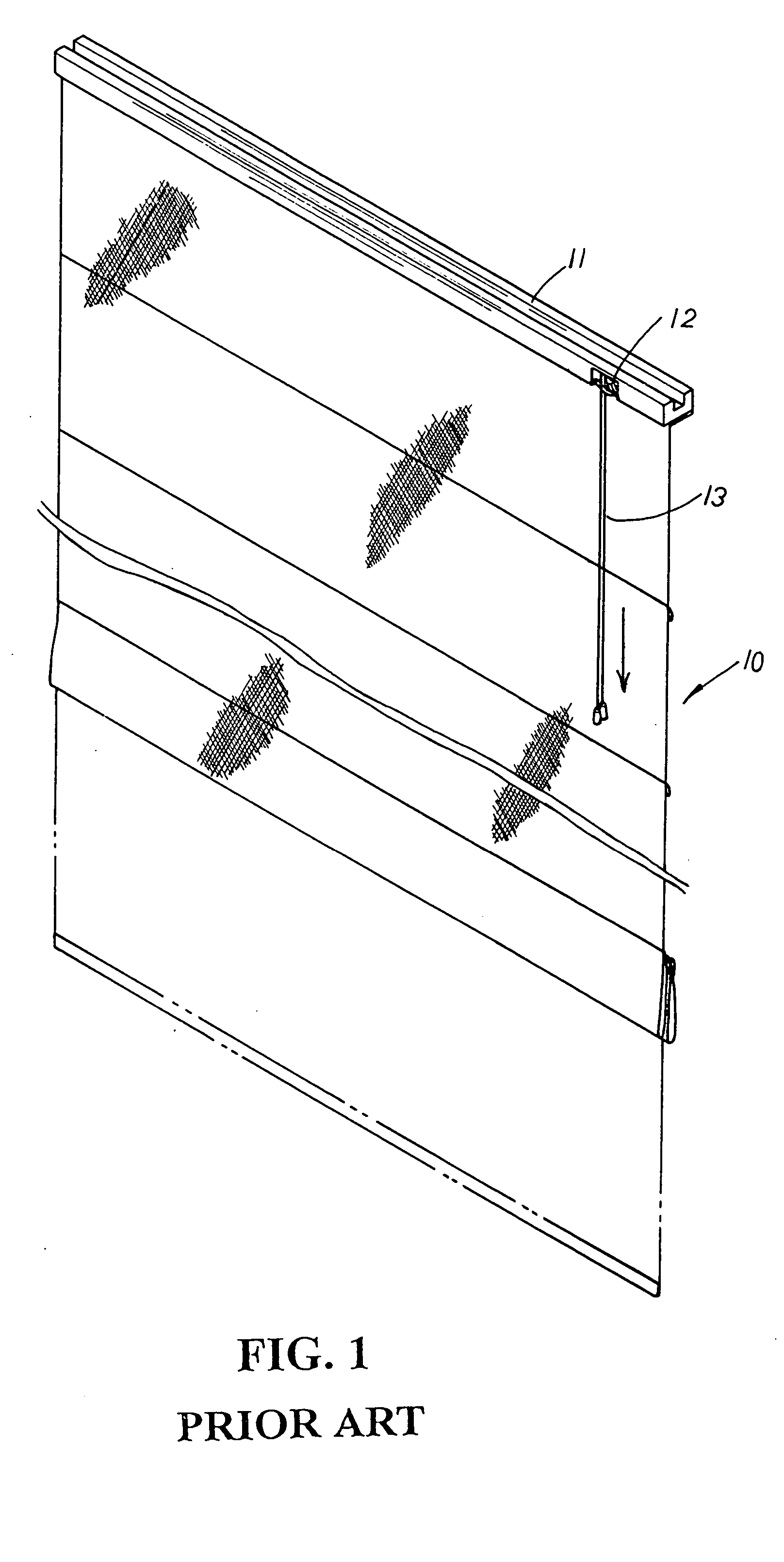
a cordless and blind technology, applied in the direction of shutters/movable grilles, door/window protective devices, wing arrangements, etc., can solve the problems of a conventional blind structure posing a potential danger to children in the household, children playing around the blind may easily get caught by the suspending pull cord, etc., to save materials and assembly time, fold up or unfold easily and quickly, and save the effect of materials cost and tim

Active Publication Date: 2005-05-26
CHING FENG BLINDS INC CO LTD
View PDF4 Cites 38 Cited by
  • Summary
  • Abstract
  • Description
  • Claims
  • Application Information

AI Technical Summary

Benefits of technology

[0004] It is, therefore, the primary purpose of the present invention to provide a cordless blind structure, comprising a blind body attached to the underside of an upper beam, and a plurality of magnet components equidistantly distributed from bottom to top of the blind body thereof wherein, via the magnet components, the blind body is easily and precisely folded up or unfolded without any other volute wheel unit, pull cords or T-shaped cords applied thereto, economically saving the cost of materials as well as the time of assembly.
[0005] It is, therefore, the second purpose of the present invention to provide a cordless blind structure wherein the blind body is easily and quickly folded up or unfolded via the magnet components without any pull cords applied thereto, preventing children from getting caught therein to protect the safety of the household.
[0006] It is, therefore, the third purpose of the present invention to provide a cordless blind structure wherein, to collect the blind body upward, the magnet components are consecutively piled up in line from bottom to top with each magnet component securely fastened to the immediate magnet components in juxtaposition thereby, precisely folding up and fixing the blind body at a desired position. And to unfold the blind body thereof, the blind body is pulled slightly downwards by the bottommost slat thereof to detach the engaged magnet components from one another for the blind body to suspend naturally downwards in display, facilitating the operation of the present invention in an easy and fast manner.

Problems solved by technology

There are some drawbacks to such conventional blind structure.
Children playing around the blind may easily get caught by the suspending pull cords 13.
Thus, the conventional blind structure poses a potential danger to children in the household.

Method used


Image

  • Cordless blind structure
  • Cordless blind structure
  • Cordless blind structure

Examples


Embodiment Construction

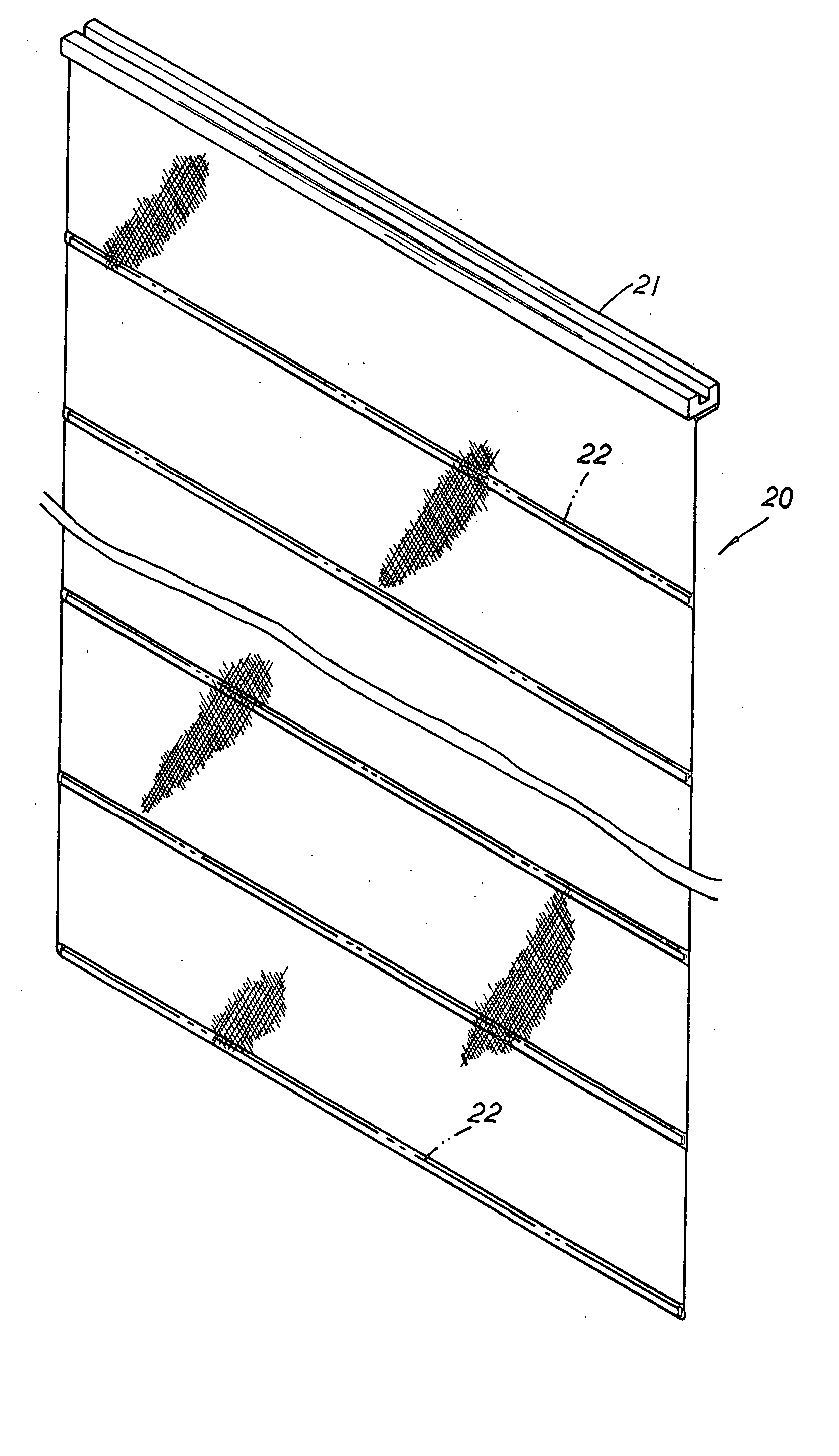
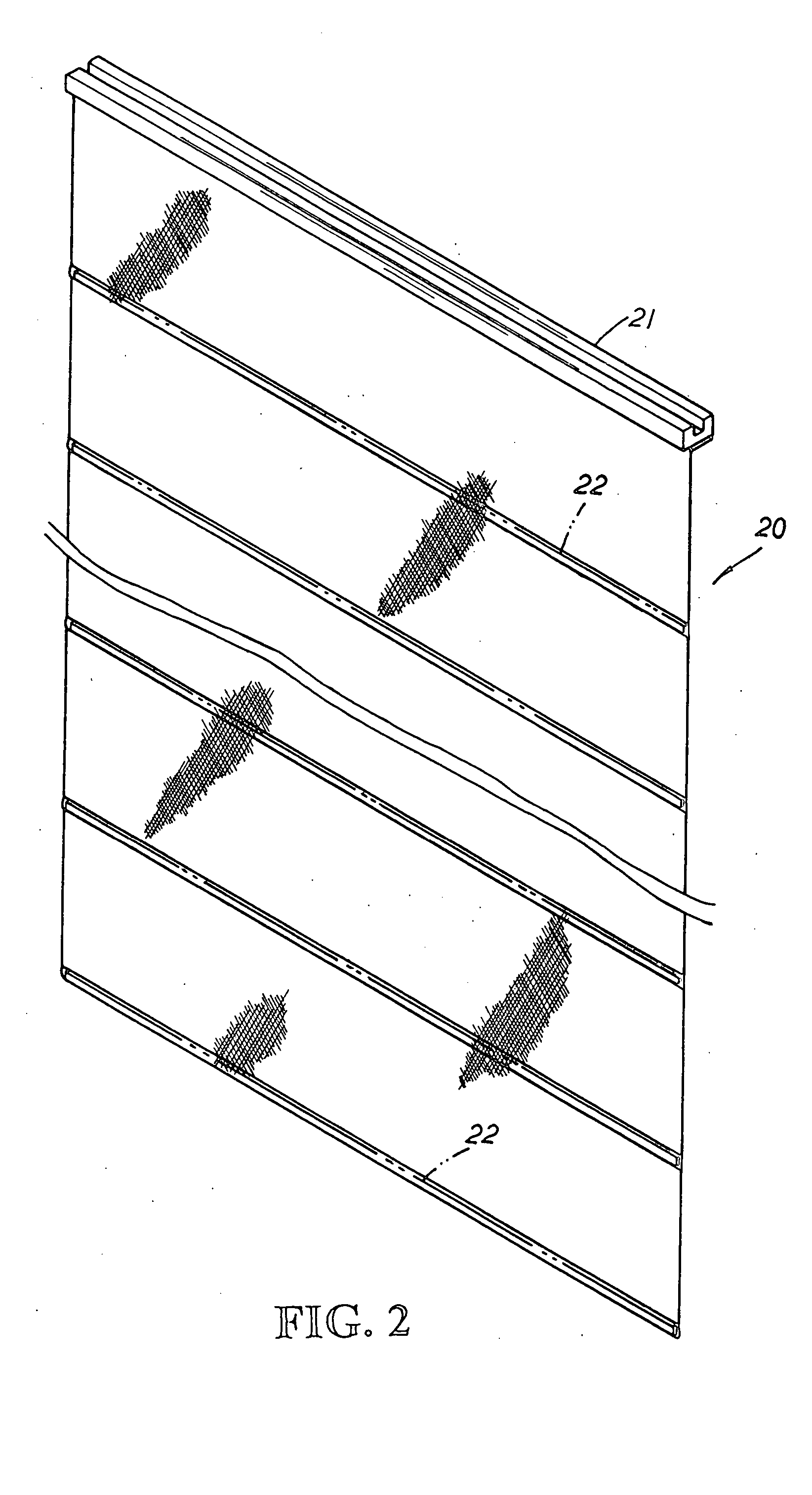
[0013] Please refer to FIGS. 2 to 4 inclusive. The present invention is related to a cordless blind structure, comprising a blind body 20 attached to the underside of an upper beam 21. A plurality of magnet components 22 such as metal or rubber magnets are equidistantly distributed from the bottommost slat upward to the top of the blind body 20 thereof. The magnet components 22 can be of elongated bars as shown in FIG. 2, or magnet components 22′ of elongated blocks 22′ can also be transversely arranged in equal space at the blind body 20 thereon as shown in FIG. 3. The magnet components 22, 22′ can be securely fixed onto the outer surface of the blind body 20 via thermal melting art as shown in FIG. 4 or sewed equidistantly inside the blind body 20 and concealed therein.

[0014] Please refer to FIG. 5. To collect the blind body 20 upward, the magnet components 22 or 22′ are consecutively lifted upwards from bottom to top to fold up the slats of the blind body 20 in half piece by pie...


PUM


Abstract

A cordless blind structure includes a blind body attached to the underside of an upper beam, and a plurality of magnet components of elongated bars or blocks equidistantly distributed from the bottommost slat upward to the top of the blind body thereof wherein the magnet components are securely fixed to the outer surface of the blind body via thermal melting art or equidistantly sewed and concealed therein. To collect the blind body upward, the magnet components are consecutively lifted upwards from bottom to top and sequentially piled up in line with each magnet component securely fastened to the immediate magnet components in juxtaposition thereby so as to precisely fold up the slats of the blind body in half piece by piece and securely fix the blind body thereof at a desired position. And to unfold the blind body thereof, the blind body is pulled slightly downwards by the bottommost slat thereof to detach the engaged magnet components from one another, releasing the collected blind body to suspend naturally downwards in display without any other pull cords or T-shaped cords applied thereto.

Description

BACKGROUND OF THE INVENTION [0001] The present invention is related to a cordless blind structure, comprising a blind body attached to the underside of an upper beam, and a plurality of magnet components equidistantly distributed from bottom to top of the blind body thereof wherein the magnet components are securely fixed to the outer surface of the blind body via thermal melting art or equidistantly sewed and concealed therein. To collect the blind body upward, the magnet components are consecutively piled up in line from bottom to top with each magnet component securely fastened to the immediate magnet components in juxtaposition thereby, precisely folding up and fixing the blind body at a desired position. And to unfold the blind body thereof, the blind body is pulled slightly downwards to detach the engaged magnet components from one another, releasing the collected blind body to suspend naturally downwards in display without any other pull cords or T-shaped cords applied theret...

Claims


Application Information

Patent Timeline
Patent Type & Authority Applications(United States)
IPC IPC(8): E06B9/262
CPCE06B2009/2622E06B9/262
Inventor HSU, BEN
Owner CHING FENG BLINDS INC CO LTD
Why Eureka
Try Eureka