
Steerable drilling system

Active Publication Date: 2005-05-26
SCHLUMBERGER TECH CORP
View PDF17 Cites 72 Cited by
  • Summary
  • Abstract
  • Description
  • Claims
  • Application Information

AI Technical Summary

Benefits of technology

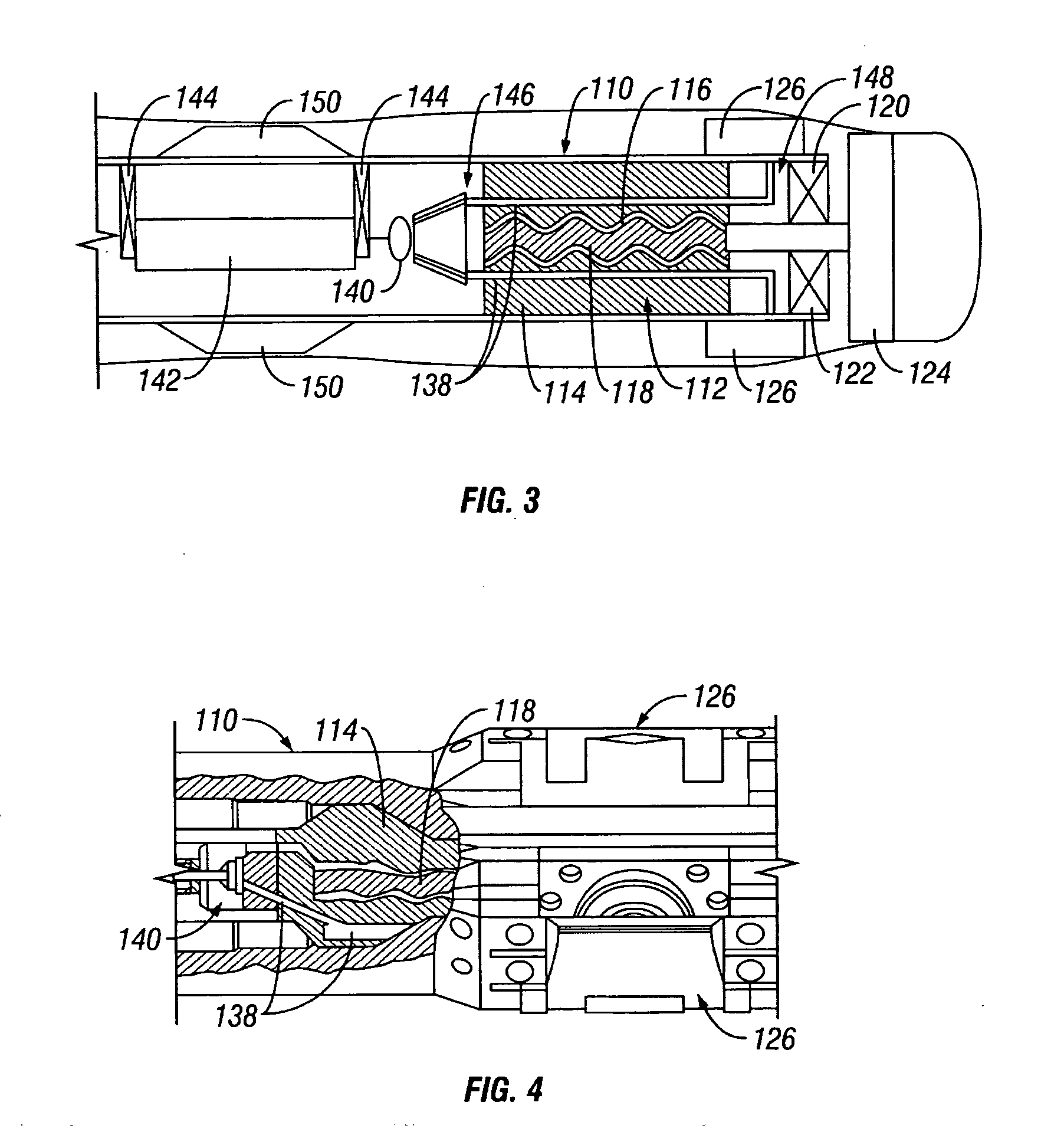
[0015] Such an arrangement is advantageous in that the bias unit operates by making use of the fluid pressure drop caused by the provision of the downhole motor. As a result, the system may be used to achieve steerable drilling in applications in which drilling fluid pressure is restricted.
[0016] The valve arrangement is preferably located at the upstream region, along with a control unit for controlling the operation thereof. This has the advantage that, in the event of a lost hole-type event, it may be possible to recover the control unit.

Problems solved by technology

In some applications, the pressure at which drilling fluid can be supplied is restricted and, where other downhole components also require a pressure drop to operate correctly or efficiently, it may be undesirable or impractical to use a bias unit of this type.
However, the use of such motors in conjunction with bias units of the type mentioned hereinbefore is problematic as the control unit for the bias unit is located between the motor and the bias unit resulting in these components being spaced apart from one another by a significant distance.
This can limit achievable build and turn rates.

Method used


Image

  • Steerable drilling system
  • Steerable drilling system
  • Steerable drilling system

Examples


Embodiment Construction

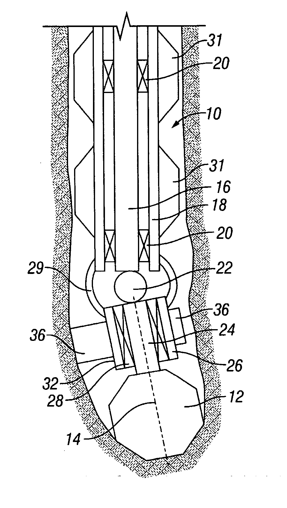
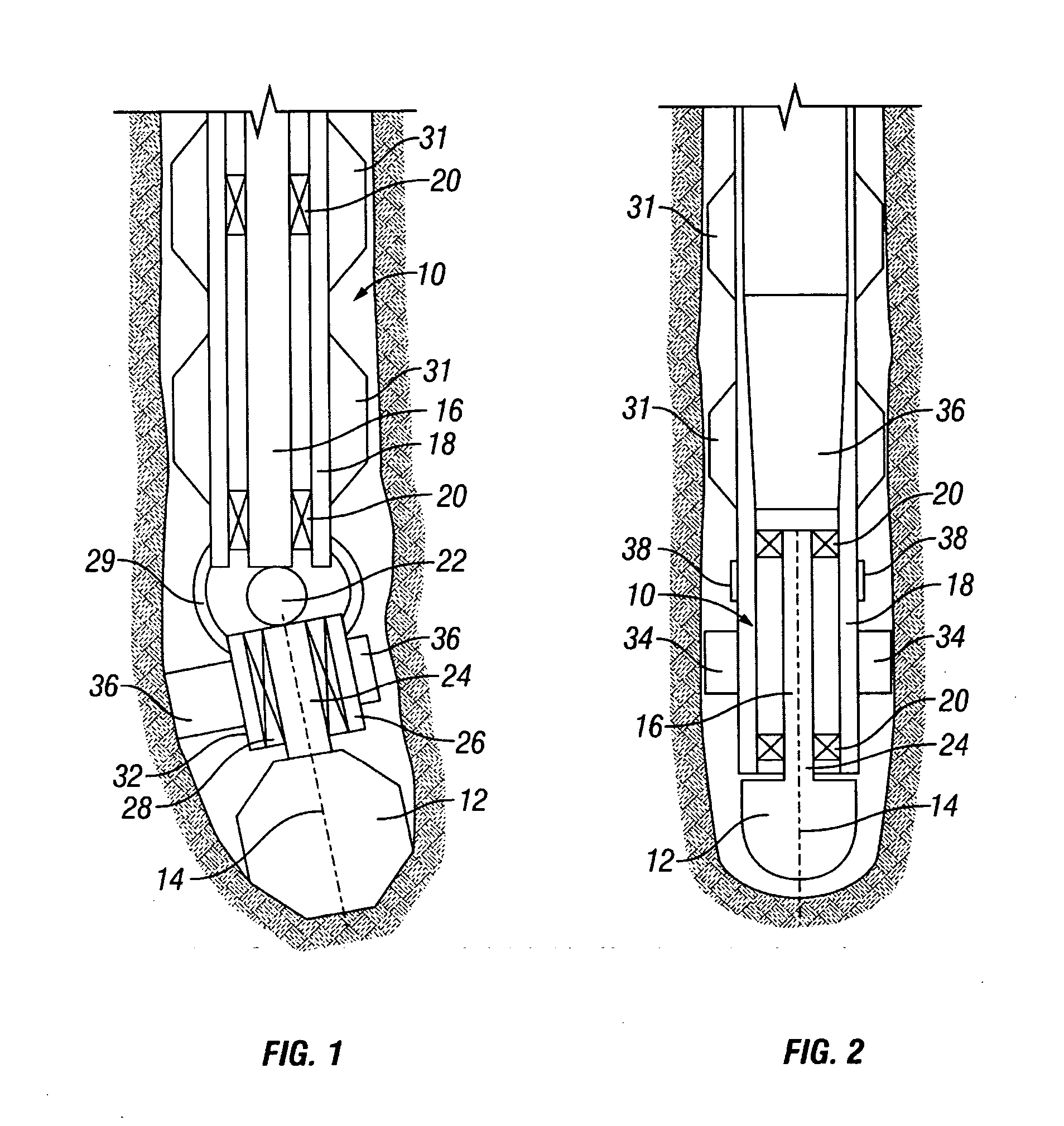
[0024] Referring firstly to FIG. 1, a steerable system for use in the formation of a wellbore is shown. The steerable system comprises a downhole motor 10 arranged to drive a drill bit 12 for rotation about an axis 14 thereof. The motor 10 is a fluid driven motor and comprises a rotor 16 rotatable within a generally cylindrical stator 18. The rotor 16 is supported for rotation within the stator 18 by bearings 20. The outer surface of the rotor 16 and the inner surface of the stator 18 are provided with formations which cooperate with one another to define a series of cavities which are isolated from one another and which progress along the length of the motor 10 as the rotor 16 rotates relative to the stator 18. A progressive cavity motor of this type is sometimes referred to as a Moineau motor.

[0025] The stator 18 of the motor 10 is connected to the drill string by which the steerable system is carried so as to be rotatable therewith. The rotor 16 is connected through a universal ...


PUM


Abstract

A steerable system comprises a fluid powered motor 10 having a rotor 16 and a stator 18, and a bias arrangement having a plurality of bias pads 34 connected to the stator 18 so as to be rotatable therewith, the bias pads 34 being moveable to allow the application of a side load to the steerable system.

Description

CROSS REFERENCE TO RELATED APPLICATIONS [0001] This application claims priority from UK Patent Application Number 0327434.7 filed Nov. 26th, 2003. BACKGROUND OF THE INVENTION [0002] This invention relates to a steerable drilling system and components thereof for use in the formation of, for example, a wellbore for use in the extraction of hydrocarbons. [0003] A known steerable drilling system comprises a downhole motor used to drive a drill bit for rotation about an axis thereof. A bias unit is located between the motor and the drill bit and arranged to apply a biassing, sideways acting load to the drill bit to urge the drill bit form a curve in the borehole being drilled. The bias unit typically comprises a housing upon which a number of moveable, for example pivotable, flaps or pads are mounted, and actuators in the form of pistons associated with the pads to drive the pads between retracted and extended positions. A control unit is provided to control the operation of the actuato...

Claims


Application Information

Patent Timeline
IPC IPC(8): E21B7/06E21B17/10
CPCE21B17/1014E21B7/062E21B7/068
Inventor DOWNTON, GEOFF
Owner SCHLUMBERGER TECH CORP
Features
  • Generate Ideas
  • Intellectual Property
  • Life Sciences
  • Materials
  • Tech Scout
  • Unparalleled Data Quality
  • Higher Quality Content
  • 60% Fewer Hallucinations
Learn More