Shock and vibration isolation system

Active Publication Date: 2005-06-02
THE BOEING CO
View PDF8 Cites 6 Cited by
  • Summary
  • Abstract
  • Description
  • Claims
  • Application Information

AI Technical Summary

Benefits of technology

[0009] An exemplary damping device includes a piston and magnetized cylinder assembly filled with a magnetic damping medium, such as a Magnetorheological fluid. The action of the magnetic damping medium within the magnetized cylinder generally prov

Problems solved by technology

The stops are generally configured to stiffen and stabilize the spring mechanism when the lift-off and Max q loads

Method used


Image

  • Shock and vibration isolation system
  • Shock and vibration isolation system
  • Shock and vibration isolation system

Examples


Example

[0020] The following detailed description is merely exemplary in nature and is not intended to limit the invention or the application and uses of the invention. Furthermore, there is no intention to be bound by any expressed or implied theory presented in the preceding technical field, background, brief summary or the following detailed description.

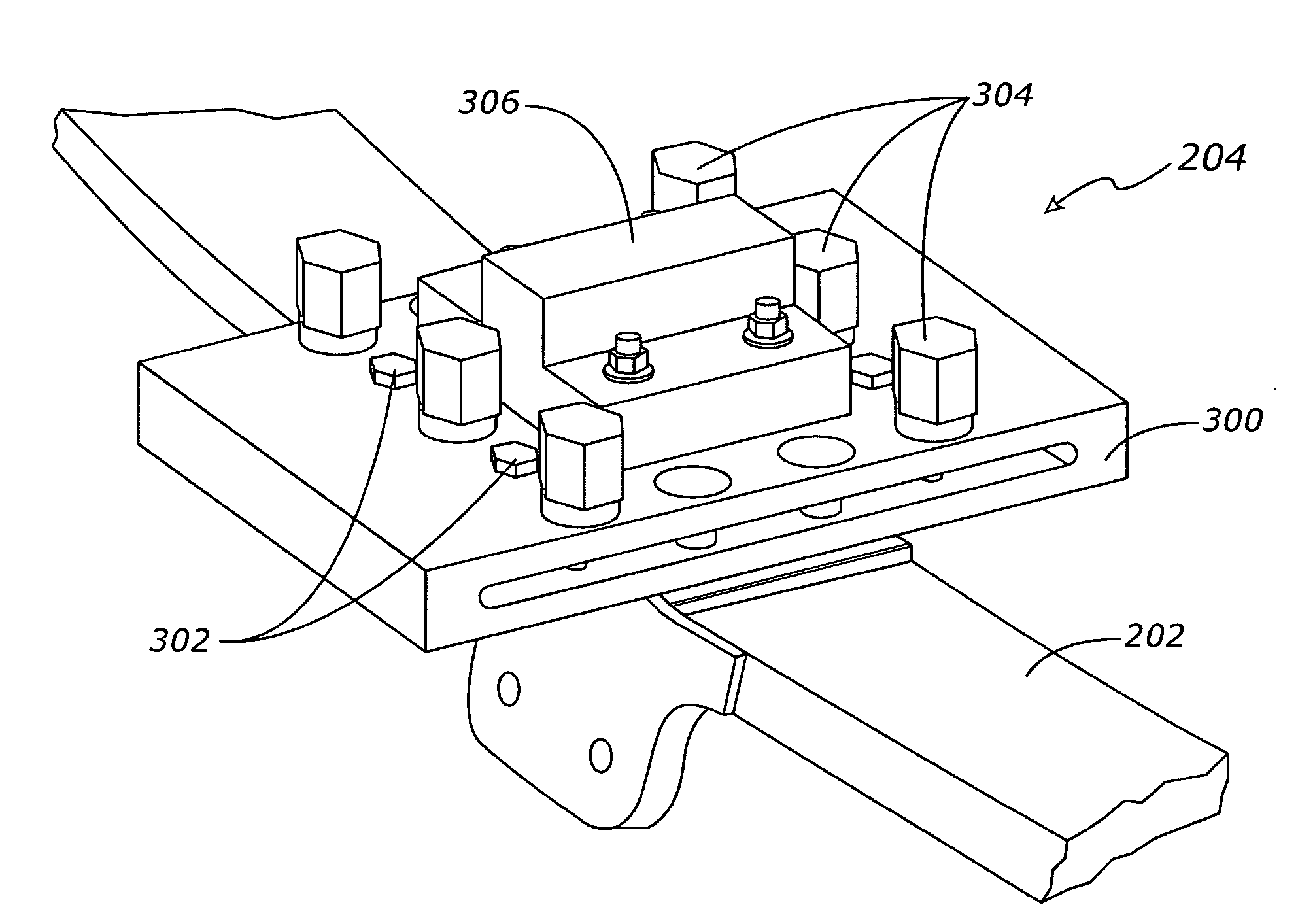
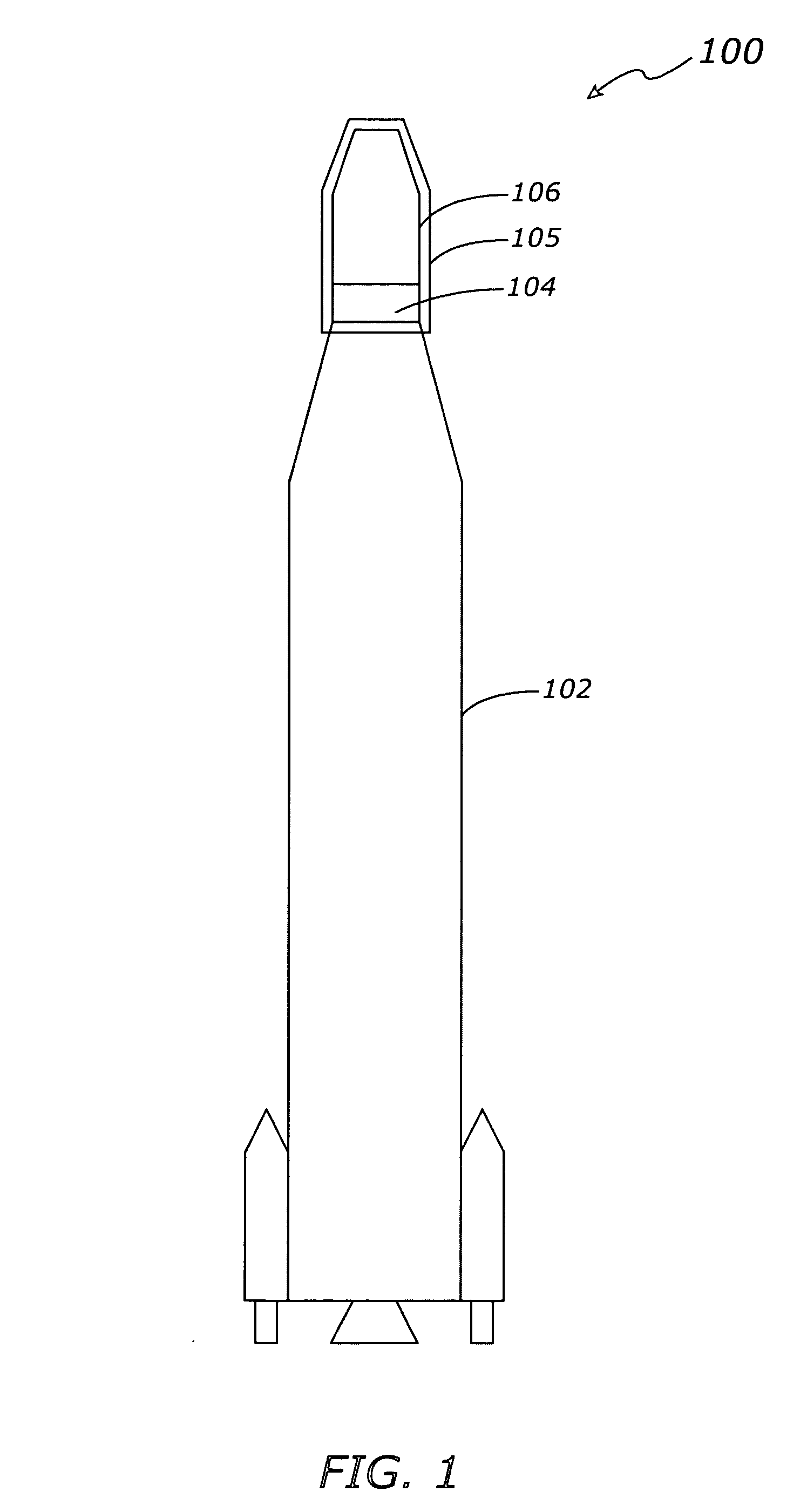
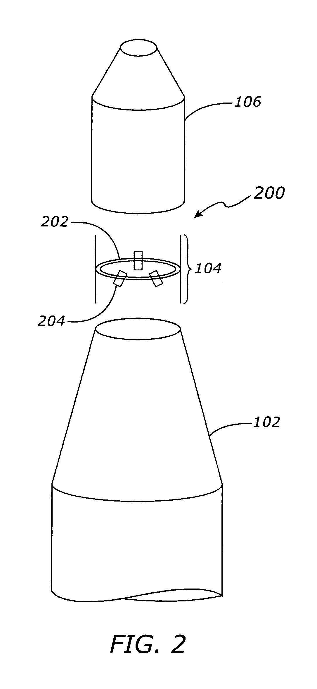
[0021] Various embodiments of the present invention pertain to the area of shock and vibration isolation between a spacecraft launch vehicle and its payload. The shock and vibration isolation system is typically incorporated into an interface assembly, which is generally connected between the payload and the launch vehicle. During the launch processes at lift-off and Max q, the isolation system within the interface assembly is configured to reduce the change in stiffness of the payload supporting structure. During the payload separation processes, the isolation system within the interface assembly is configured to reduce the shock and vi...


PUM


Abstract

An apparatus is provided for attenuating shock and vibration energy levels within a spacecraft interface isolation system. The apparatus includes one or more spring plate assemblies fitted with mechanical stops and damping devices. The isolation system is typically incorporated into an interface unit, which is connected between the launch vehicle and the payload, in order to reduce the shock and vibration load energy imposed on the payload during the fairing separation processes. The mechanical stops maintain a desired level of stiffness for the payload supporting structure during lift-off and Max q, and the damping devices reduce the spring plate oscillation tendency during fairing separation. The combination of spring plate, stop, and damping device provides a significant reduction in shock and vibration energy levels in the approximate frequency range of 100 to 300 Hz.

Description

TECHNICAL FIELD [0001] The present invention generally relates to shock and vibration isolation devices, and more particularly relates to shock and vibration isolation devices for spacecraft applications. BACKGROUND [0002] One application area of current spacecraft technology is the launching into orbit of various payloads, such as communication satellites and exploratory vehicles. For example, a Boeing Delta IV rocket may be used as a launch vehicle for a payload, such as a Eutelsat communications satellite. During the launching and separation processes (when the fairing is separated from the launch vehicle), the payload is typically subjected to significant amounts of shock and vibration stresses. The fairing is a structure that protects the payload from rain, lightning, winds, contamination and heating, until the launch vehicle reaches a very high altitude. The fairing separates from the launch vehicle when the heating rate on the payload is below a predetermined value. Under cer...

Claims


Application Information

Patent Timeline
IPC IPC(8): B64G1/64F16F9/53F16F15/06
CPCB64G1/641F16F15/06F16F9/535
Inventor TELFORD, KENNETH N.PAAVOLA, CHRIS M.
Owner THE BOEING CO
Why Eureka
Try Eureka