
Web imaging serving technology

a web-based image and database technology, applied in the field of large imaging, can solve the problems of tedious and slow display of large image databases on the internet using web browsers, large data volumes, and large data volumes, so as to simplify requests for additional image data, reduce processing time, and improve the effect of image quality

Inactive Publication Date: 2005-06-02
GRAHAM JAMES J +2
View PDF54 Cites 68 Cited by
  • Summary
  • Abstract
  • Description
  • Claims
  • Application Information

AI Technical Summary

Benefits of technology

[0006] The present invention overcomes the disadvantages and limitations of the prior art by providing a grid that is overlaid upon the image database. The grid provides a quick method for an image database to search for only the appropriate files necessary to generate an image, thereby eliminating as much unnecessary processing time as possible. Further, the grid may be used in a client applet or plug in to simplify requests for additional image data as well as very quick zoom and pan capabilities that are not limited by bandwidth restrictions.
[0010] The advantages of the present invention are that sections of enormously large image databases may be quickly and rapidly generated without time consuming searching techniques. Further, when the techniques are applied to a client / server environment, very fast panning and zooming techniques may be used.

Problems solved by technology

These databases are enormous in size and may consist of literally thousands of individual files.
Searches and other queries of these databases may be very time consuming and computationally intensive.
The display of portions of large image databases on the Internet using web browsers can also be tedious and slow due to the considerable bandwidth required for transmitting images over the Internet.
When the zoom and pan functions are very slow, users may be frustrated with the performance and either feel like they are wasting their time, not utilize the full functionality of the image, or abandon the use of the image.

Method used


Image

  • Web imaging serving technology
  • Web imaging serving technology
  • Web imaging serving technology

Examples


embodiment 100

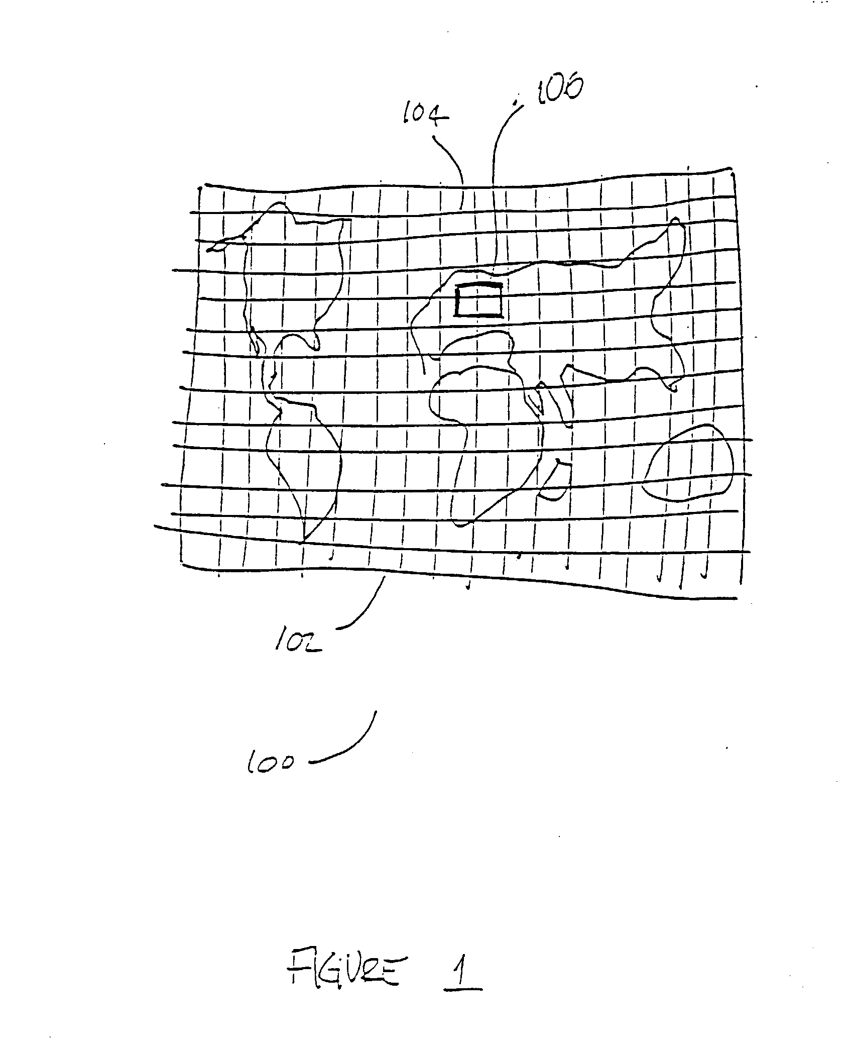
[0022]FIG. 1 illustrates an embodiment 100 of the present invention wherein a large image 102 has a grid 104 overlaid thereupon. The boundary 106 of a requested image is shown on the image 102. The grid 104 allows a fast and efficient method of determining which specific sections of the image database needs to be analyzed and retrieved to create the requested image.

[0023] The large image 102 may be a very large image database, such as a terrestrial map. Such maps are commonly terabytes in size and are time consuming to search. Further, the maps may be a compilation of many individual files. For example, an image database of a few terabytes in size may be comprised of 1000 or more individual files. Each individual file may comprise a section of the entire large image 102. When a requested area of the large image is requested, portions of several files may be required to generate the requested image.

[0024] The grid 104 is overlaid on the large image 102. Each section of the grid 104 ...

embodiment 200

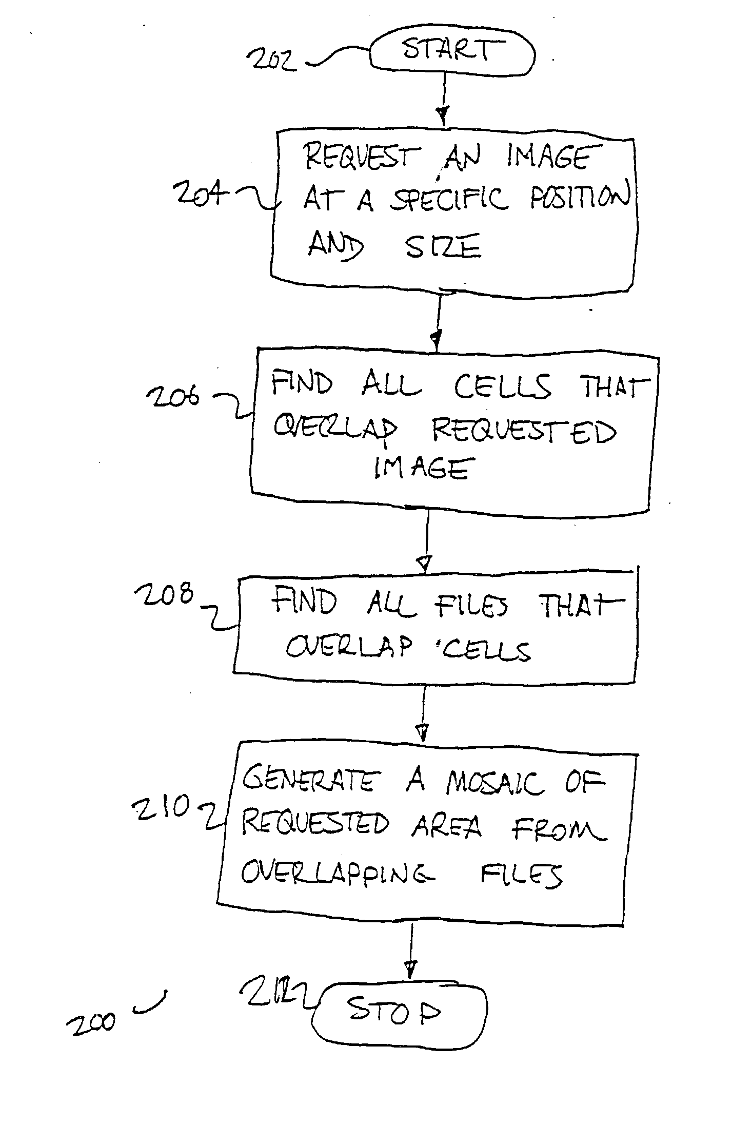
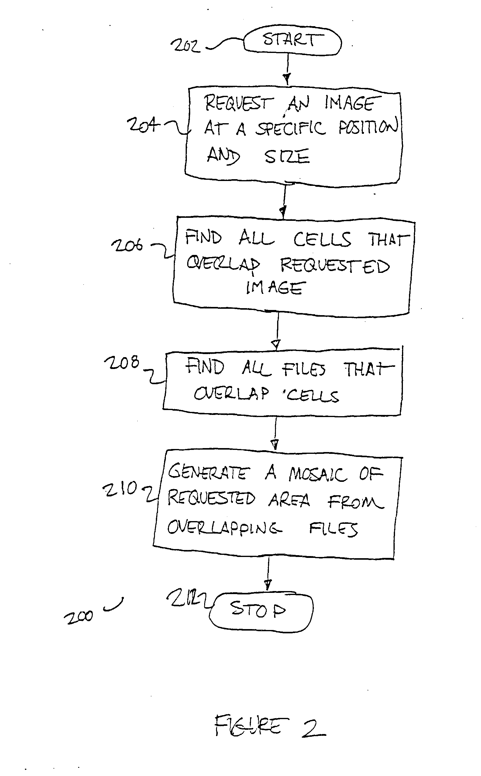
[0026]FIG. 2 illustrates an embodiment 200 of a method for quickly generating an image from a large image database using the grid illustrated in FIG. 1. After the method 200 is started 202, a request for a section of the image database is made 204, the cells that overlap the requested section is determined 206, the corresponding files are determined 208, and an image is generated from the files 210 before the method is stopped 212.

[0027] The request for a section of the image database 204 may comprise a position and size of the requested image. Further, the request may contain other parameters that may be used to determine the post processing or other manipulation of the requested image. Such parameters may include the overall size and shape of the final image, special characteristics that relate to the color, look, and feel of the image, and other parameters as may be required by any post processing of the image.

[0028] After the request is made in block 204, all of the cells that ...

embodiment 300

[0031]FIG. 3 illustrates an embodiment 300 wherein an image is requested and displayed by a web browser. The two major components are the server 302 and the client 304. The elements of the server 302 are a database 306, a set of image files 308, and a server program 310. The client 304 contains an HTML browser 312. The browser 312 sends a request to an active server page (ASP) request 314 to the server 310, which communicates with the database 306 to retrieve information to generate an image 316. The database 306 finds the necessary information from the files 308 and passes the information back to the server 310 for processing. The server 310 then generates an image 316 that is retrieved by the browser 312 for display.

[0032] The basic client / server configuration shown in the present figure is illustrative of a typical ASP web server. In this case, the embodiment is shown to generate an image on the fly. Such an embodiment may be used with the methodology described in FIGS. 1 and 2 t...


PUM


Abstract

Disclosed is a method for displaying sections of large images such as maps. A grid is placed over an image database that references the various files contained in the database. When an area is identified for a query, the cells of the grid refer only to those files to be searched that pertain directly to the query. Further, the grid reference system also allows panning and zooming of the image to be dynamic and virtually instantaneous without limitation to the bandwidth of an Internet connection.

Description

CROSS REFERENCE TO RELATED APPLICATIONS [0001] This application is based upon and claims the benefit of U.S. provisional application No. 60 / 370,083, entitled “Web Imaging Serving Technology,” filed Apr. 4, 2002 by James J. Graham and Dallen Campbell, the entire disclosure of which is herein specifically incorporated by reference for all that it discloses and teaches.BACKGROUND OF THE INVENTION [0002] a. Field of the Invention The present invention pertains generally to large imaging and specifically to the storage, retrieval, and display of large images. [0003] b. Description of the Background Maps and other large image databases are being used on the Internet for various purposes. These databases are enormous in size and may consist of literally thousands of individual files. Searches and other queries of these databases may be very time consuming and computationally intensive. [0004] The display of portions of large image databases on the Internet using web browsers can also be te...

Claims


Application Information

Patent Timeline
Patent Type & Authority Applications(United States)
IPC IPC(8): G06F17/30G06T17/05G09G5/00
CPCG06F17/30241G06T17/05G06F17/30905G06F17/3028G06F16/29G06F16/51G06F16/9577
Inventor GRAHAM, JAMES J.CAMPBELL, DALLENHARRISON, CRAIG D.
Owner GRAHAM JAMES J
Learn More