Connector for high-speed communications

a high-speed communication, electrical connector technology, applied in the direction of coupling device connection, connection contact member material, coupling protective earth/shielding arrangement, etc., can solve the problem of unsatisfactory cross talk between nearby signals, one signal causing electrical interference, and it is difficult to provide both high signal contact pin density and acceptable cross talk levels

Inactive Publication Date: 2005-06-02
FCI AMERICAS TECH LLC
View PDF21 Cites 110 Cited by
  • Summary
  • Abstract
  • Description
  • Claims
  • Application Information

AI Technical Summary

Problems solved by technology

Often, the signal connections are so closely spaced that undesirable cross talk occurs between nearby signals.
That is, one signal induces electrical interference to a nearby signal.
With such wider signal conductors and conventional grounding, it becomes difficult to provide both high signal contact pin density and acceptable cross talk levels.

Method used


Image

  • Connector for high-speed communications
  • Connector for high-speed communications
  • Connector for high-speed communications

Examples


Embodiment Construction

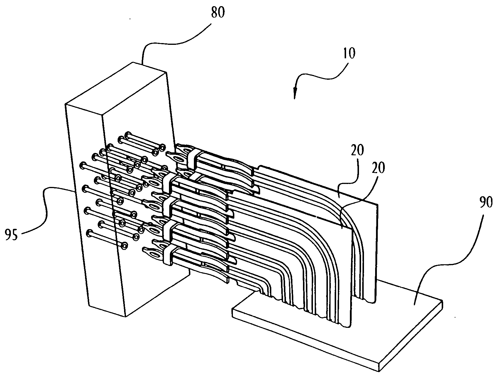
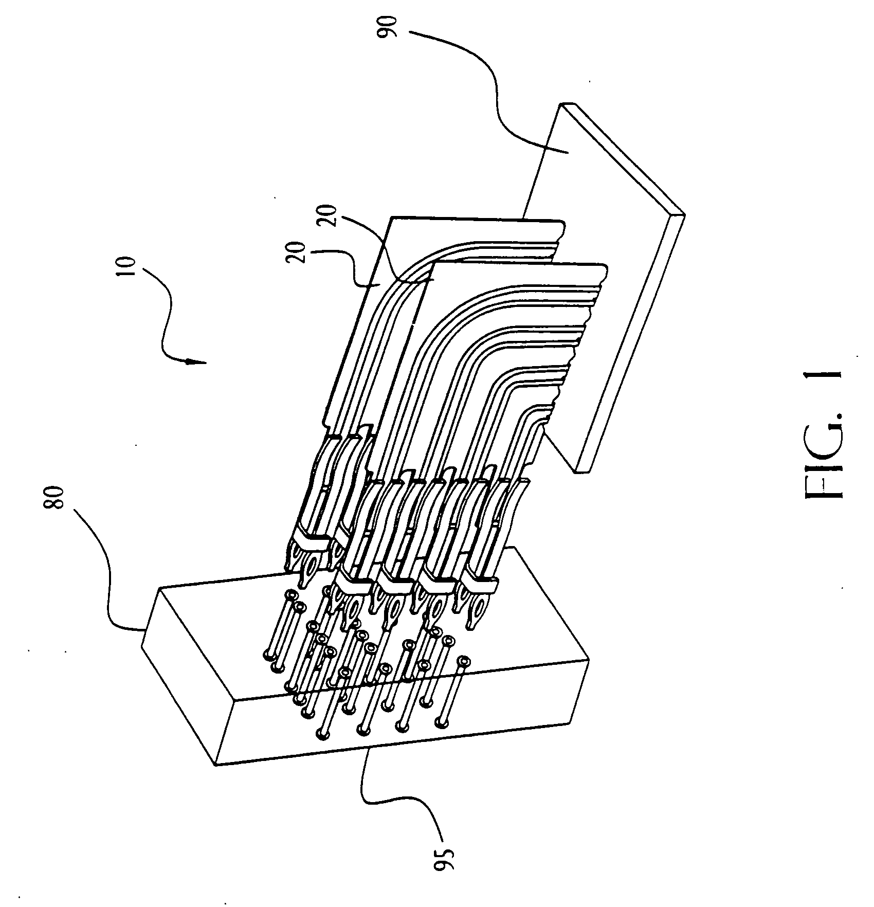
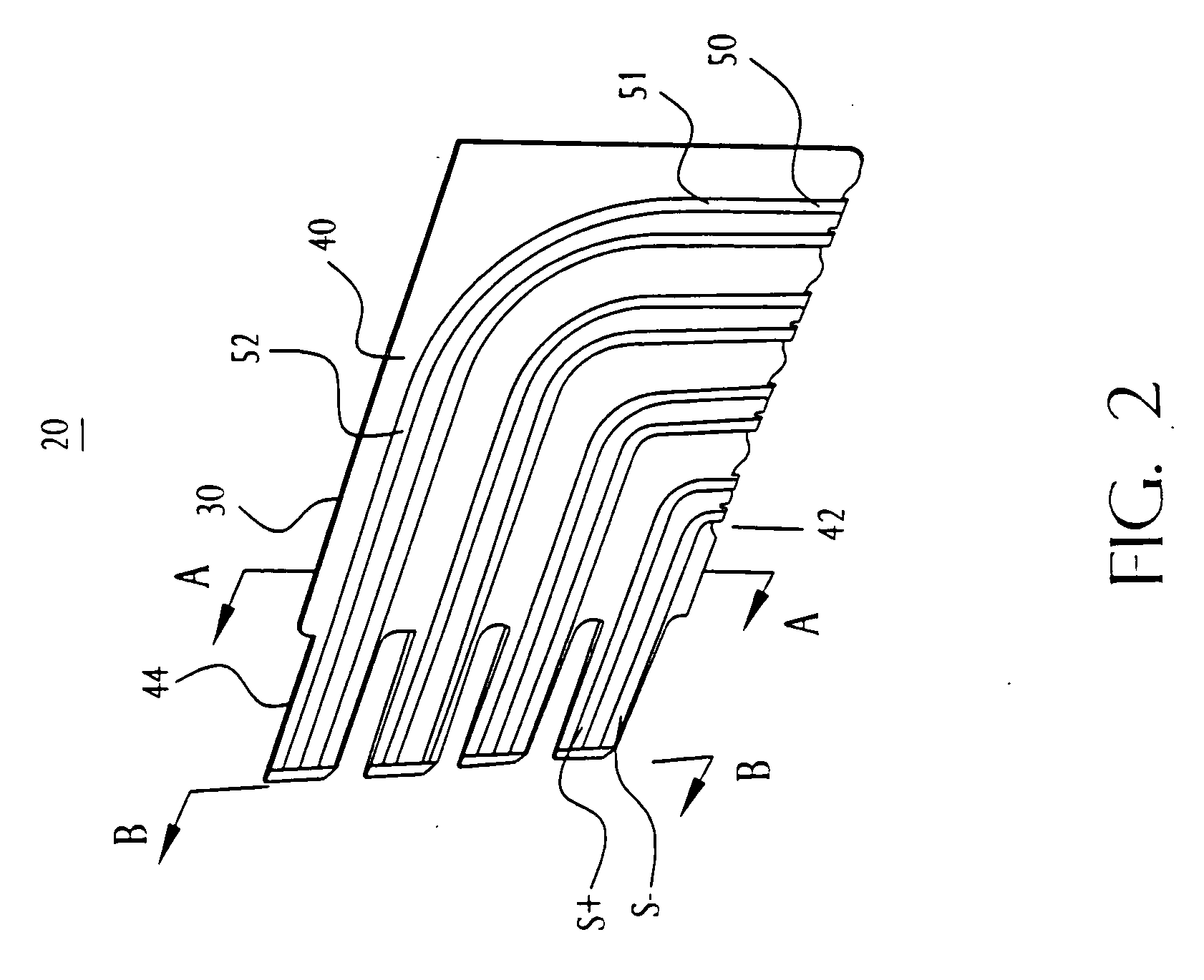
[0020] The invention is directed to a high speed electrical connector comprising a substantially planar dielectric, a substantially planar ground plane, and signal conductor. The ground plane is disposed on one planar surface of the dielectric and the signal conductor is disposed on the other planar surface of the dielectric.

[0021] Certain terminology may be used in the following description for convenience only and is not considered to be limiting. For example, the words “left”, “right”, “upper”, and “lower” designate directions in the drawings to which reference is made. Likewise, the words “inwardly” and “outwardly” are directions toward and away from, respectively, the geometric center of the referenced object. The terminology includes the words above specifically mentioned, derivatives thereof, and words of similar import.

[0022]FIG. 1 is a perspective view of an illustrative electrical connector (without a housing) and illustrative receptacle, in accordance with an embodiment...


PUM

PropertyMeasurementUnit
complementary voltageaaaaaaaaaa
thicknessaaaaaaaaaa
thicknessaaaaaaaaaa

Abstract

A high speed electrical connector is provided that comprises a substantially planar dielectric, a substantially planar ground plane, and a signal conductor. The ground plane is disposed on one planar surface of the planar dielectric and the signal conductor is disposed on the opposing planar surface of the planar dielectric.

Description

FIELD OF THE INVENTION [0001] The invention relates in general to electrical connectors. More particularly, the invention relates to electrical connectors for high speed communications. BACKGROUND OF THE INVENTION [0002] Electrical connectors provide signal connections between electronic devices. Often, the signal connections are so closely spaced that undesirable cross talk occurs between nearby signals. That is, one signal induces electrical interference to a nearby signal. With electronic device miniaturization and high speed electronic communications becoming more prevalent, cross talk becomes a significant factor in connector design. In order to reduce cross talk between signals, it is known to provide grounding connection pins in such connectors. However, as communication speeds increase, wider signal conductors are typically used. With such wider signal conductors and conventional grounding, it becomes difficult to provide both high signal contact pin density and acceptable c...

Claims


Application Information

Patent Timeline
Patent Type & Authority Applications(United States)
IPC IPC(8): H01R12/72H01R13/514H01R13/6471H01R13/6477H01R13/648H01R13/6586
CPCH01R12/728H01R13/6471H01R13/6477Y10T29/49147Y10T29/49222Y10T29/49153H01R13/6586H01R13/514
Inventor EVANS, ROBERT F.
Owner FCI AMERICAS TECH LLC
Why Eureka
Try Eureka