

Humanoid robotics
a humanoid robot and robotic technology, applied in the field of humanoid robots, can solve the problems of limited number, inability to perform many of the movements desired, and dexterity of the prior art robotic hand,
- Summary
- Abstract
- Description
- Claims
- Application Information
AI Technical Summary
Problems solved by technology
Method used
Image

Examples
Embodiment Construction
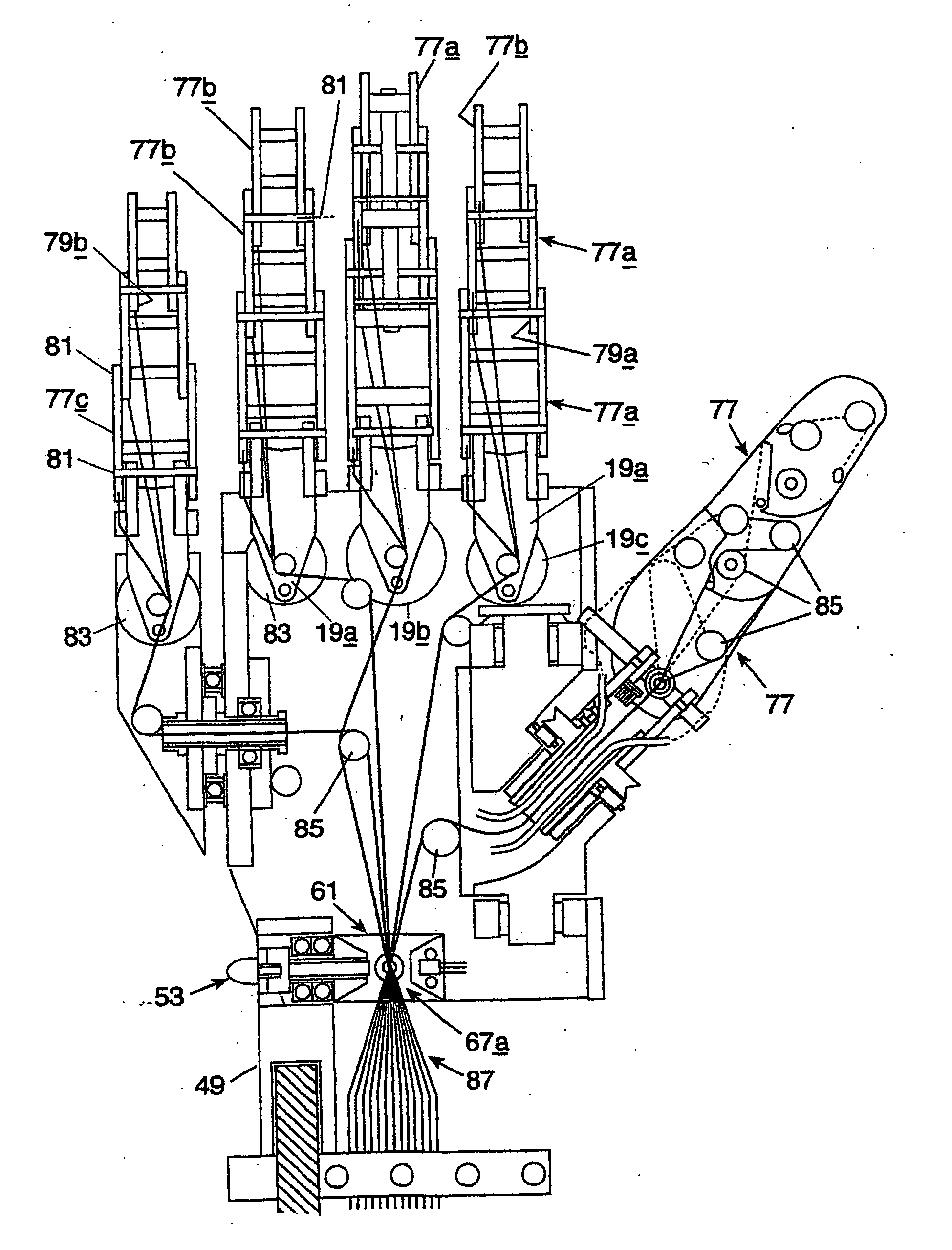
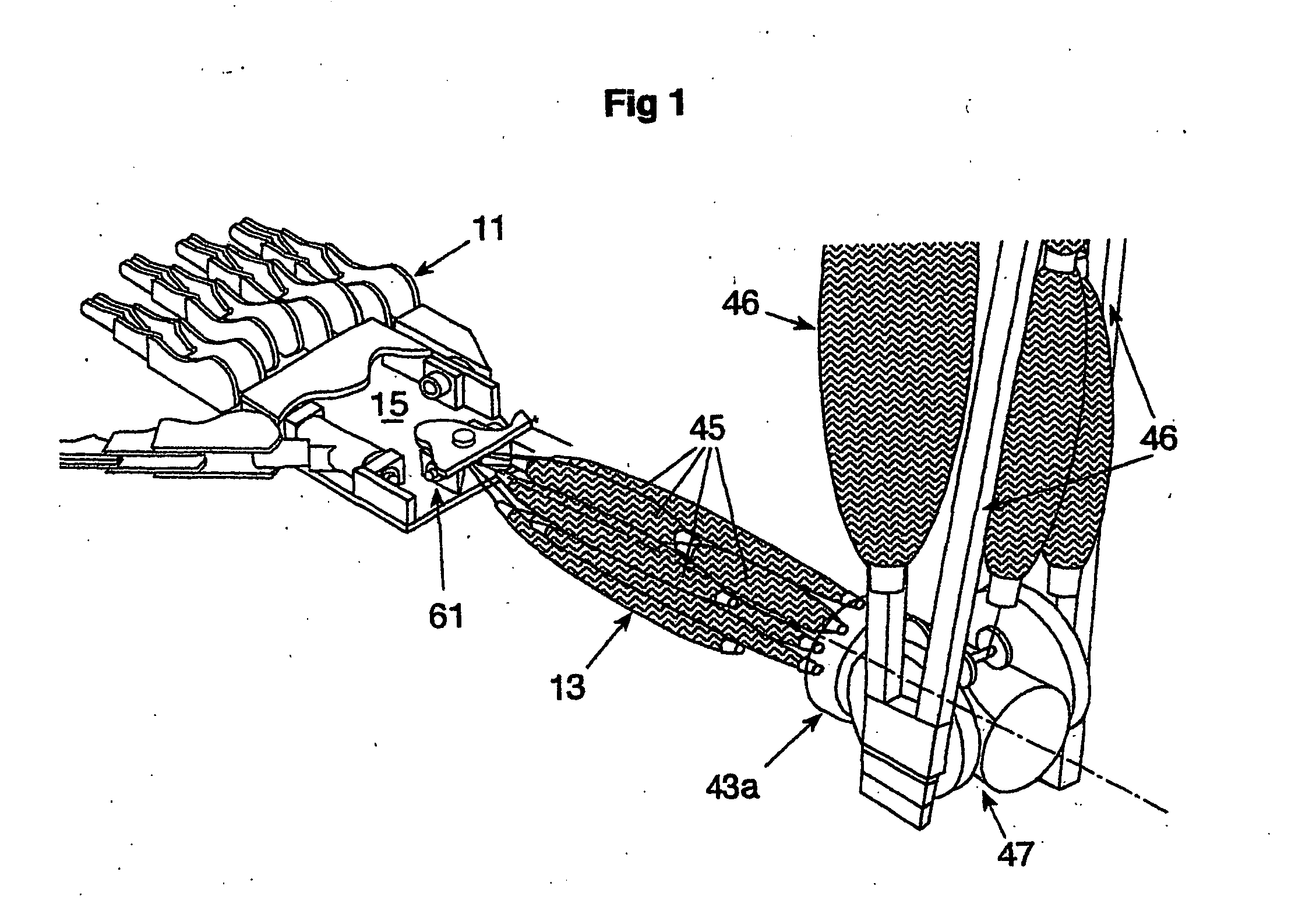
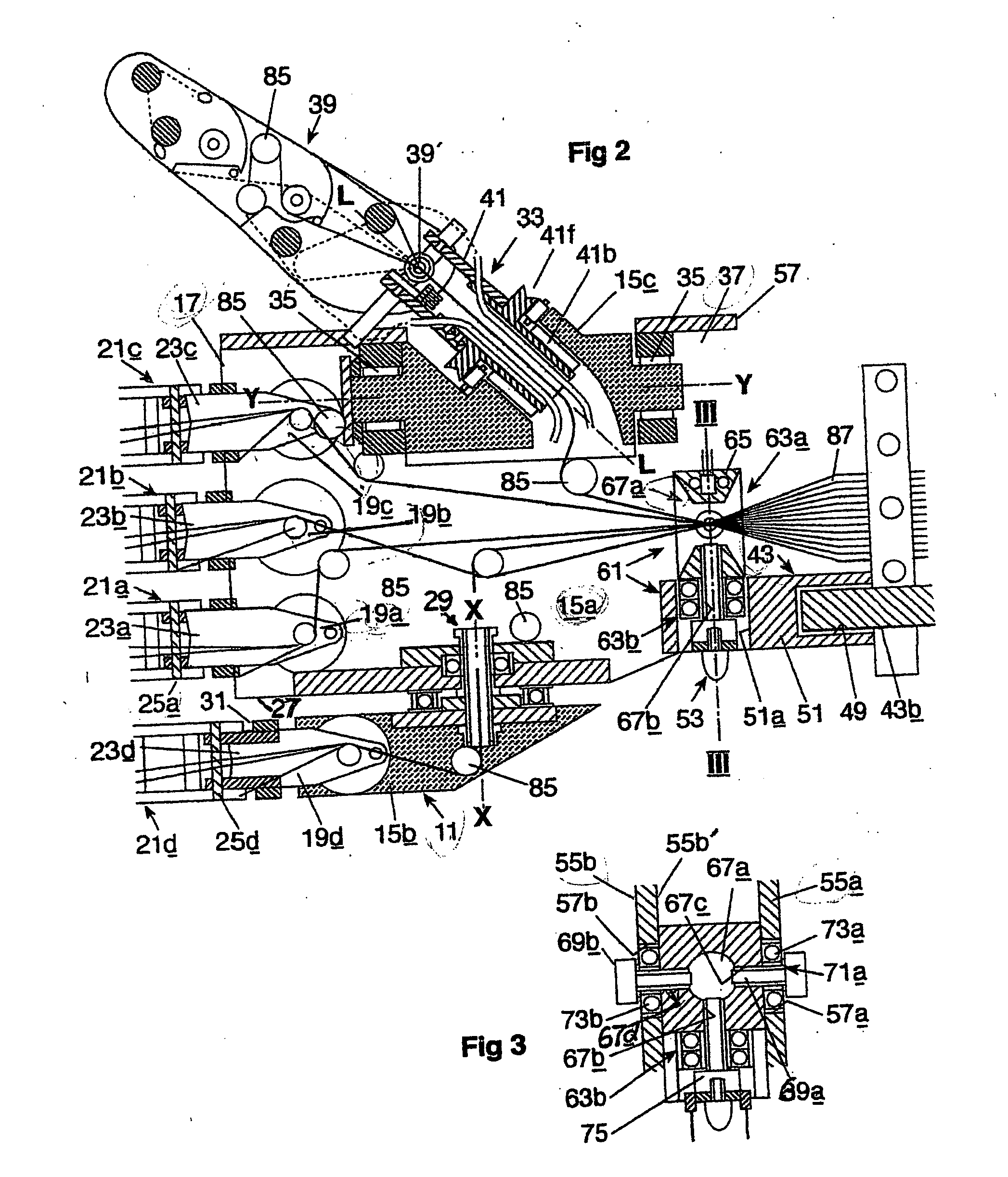
[0024] The robotic forearm and hand configuration comprises: a hand portion 11, a forearm portion 13, and means incorporated in said forearm 13 and operative to produce local relative angular movements in the several movable parts of the forearm and hand configuration, all as hereinafter described. The hand portion 11 comprises: a rigid-main palm part 15a; projecting from said palm part 15a at a transversely extensive forward boundary 17 thereof, rigid first, second, and third link elements 19a, 19b, 19c, respectively; first, second and third finger-simulating digits, 21a, 21b, 21c, respectively; first and second auxiliary palm parts 15b, 15c, respectively; a rigid fourth link element 19d; a finger-simulating fourth digit 21d; and a fifth or thumb-simulating digit.
[0025] The link elements 19a, 19b, 19c, are respectively pivotally coupled at side by side positions to the main palm part 15 at or adjacent to said forward boundary 17 in such manner as to permit angular movement of said...
PUM
 Abstract
Description
Claims
Application Information