Ink jet printing apparatus and ink jet printing method

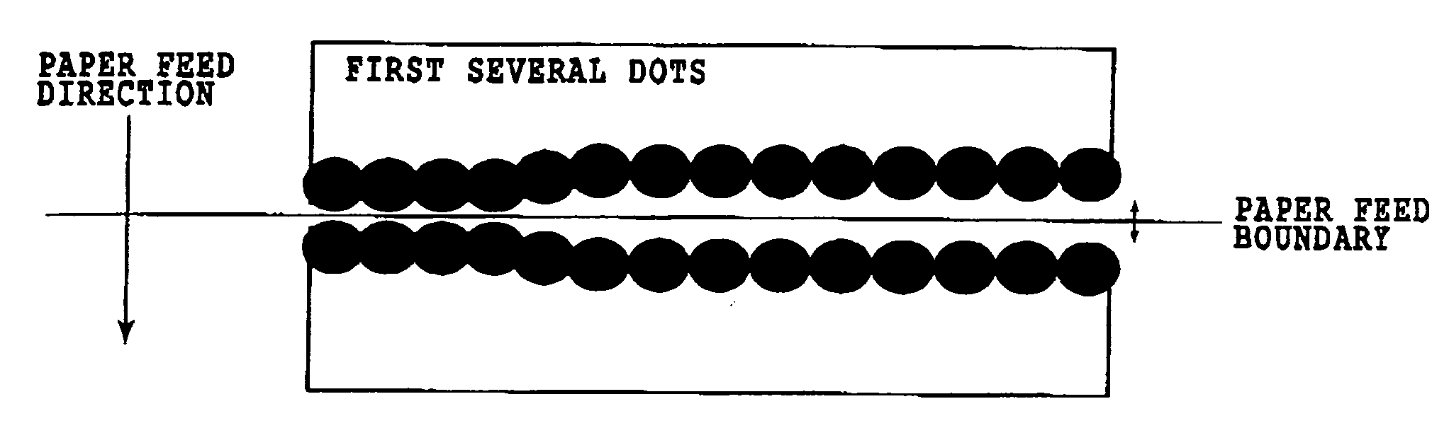
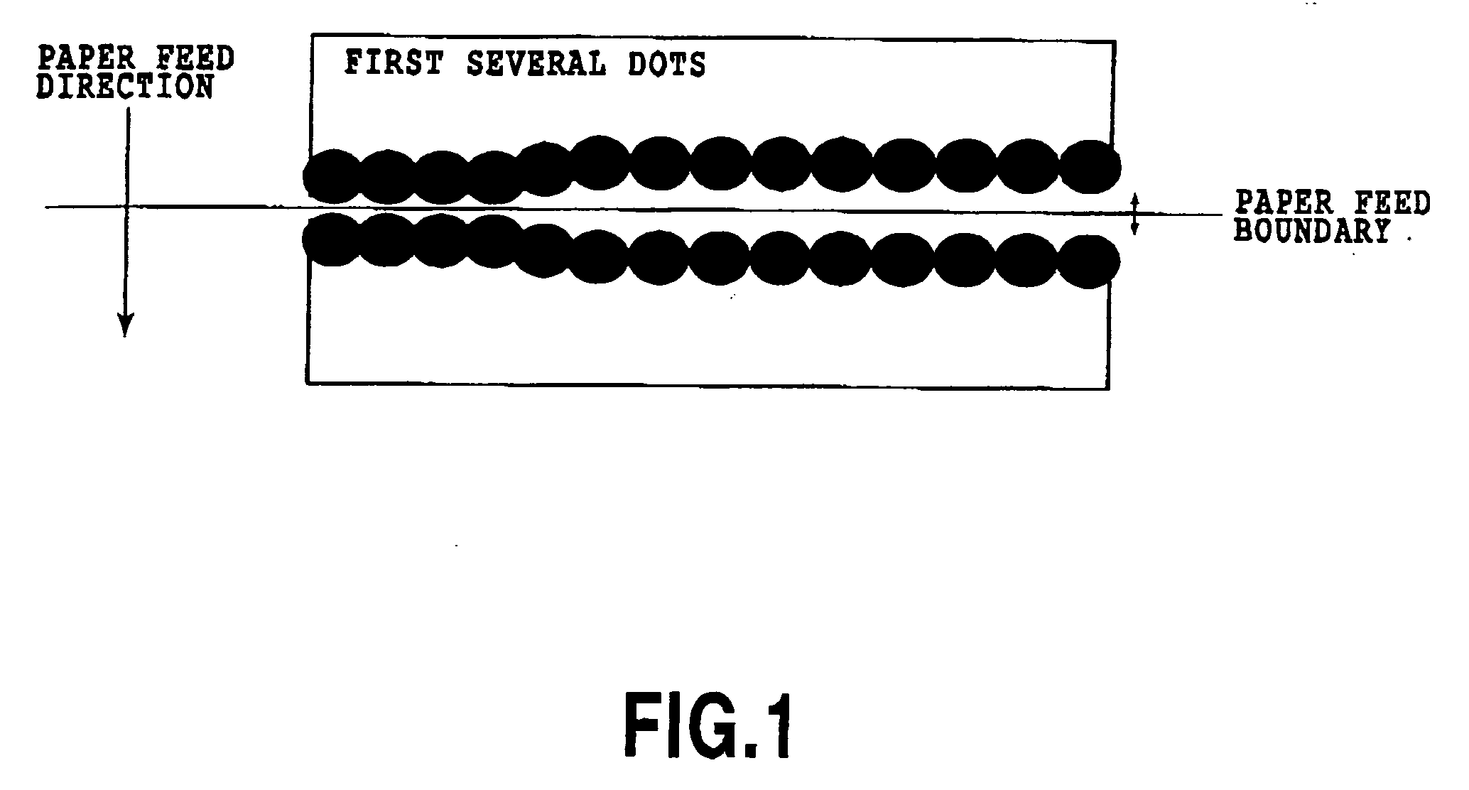
a printing apparatus and ink jet technology, applied in the field of ink jet printing apparatus, can solve the problems of inability to print simple images with a low print density, serious problems such as “end dot deflection” and other problems, and achieve the effect of less visual conspicuous

Inactive Publication Date: 2005-06-09
CANON KK
View PDF5 Cites 32 Cited by
  • Summary
  • Abstract
  • Description
  • Claims
  • Application Information

AI Technical Summary

Benefits of technology

[0024] The present invention has been accomplished to solve the above problems and to provide an ink jet printing apparatus and an ink jet printing method whi

Problems solved by technology

The printing apparatus using small-volume ink dots, however, may encounter new problems, such as variations in dot landing positions and unstable ejections.
However, if a print head with a high nozzle density and small ink droplets is used, this phenomenon does not occur as long as the printing density is not high enough.
As described above, in ink jet printing apparatus of recent years that eject small ink droplets at a high resolution, the “end dot deflection” poses a serious problem.
However, since the method of Japanese Patent Application Laid-open No 8-025693 (1996) is not intended specifically for the “end dot deflection,” this method may give rise to another problem where the mend dot deflection” phenomenon does not exist.
Further, since in the serial type printing apparatus, the greater the overlapping area t

Method used


Image

  • Ink jet printing apparatus and ink jet printing method
  • Ink jet printing apparatus and ink jet printing method
  • Ink jet printing apparatus and ink jet printing method

Examples


first embodiment

[0052] Now, a first embodiment of this invention will be described in detail.

[0053]FIG. 5 is a perspective view showing a construction of an ink jet print head applicable to this embodiment. In FIG. 5, a print head H1000 comprises mainly a nozzle unit H1001 having a functional structure related to ink ejection and an ink supply unit H1002 for supplying ink to the nozzle unit H1001.

[0054]FIG. 6 is an exploded perspective view of the print head H1000 disassembled into the nozzle unit H1001 and the ink supply unit H1002. In the figure, an opening of an ink supply member H1500 and the nozzle unit M1001 are sealed with a third sealant H1503 to hermetically close a common ink chamber H1501. A Z reference plane H1502 of the ink supply member H1500 and a Z-direction reference H1206 of the nozzle unit H1001 are positioned and fixed together by screws 1900. The third sealant H1503 preferably has an ink resistance, hardens at a normal temperature and is flexible enough to withstand a linear ...

second embodiment

[0105] A second embodiment of this invention will be described as follows. The basic construction of the printing apparatus applied in this embodiment is similar to that of the first embodiment explained with reference to FIG. 6 to FIG. 14.

[0106]FIG. 20 is a schematic diagram showing an arrangement of nozzle substrates H1100A and H1100B in this embodiment and an array of dots to produce a desired print density.

[0107] A print head used in this embodiment is capable of printing at 1,200 dpi, so the pitch of the nozzles is about 20 μm, which in this figure is represented by a distance Pn. It is noted that in the overlapping regions of the two nozzle substrates H1100A and Hl100B, these nozzle substrates have different pitches of the nozzles H1105. All the nozzles H1105A in the nozzle substrate H1100A and the nozzles H1105B in the nozzle substrate HI100B except the left end portion are arranged at the Pn pitch. Of the nozzles in the nozzle substrate HI100B, those nozzles H1105B lying i...

third embodiment

[0112] A third embodiment of this invention will be described as follows. The printing apparatus applied in this embodiment is also similar in basic construction to the above embodiment explained with reference to FIG. 6 to FIG. 14.

[0113]FIG. 21 is a schematic diagram showing an arrangement of nozzle substrates H1100A and H1100B in this embodiment.

[0114] The nozzle substrates H1100A and HI100B applied in this embodiment have the same arrangement of nozzles as that of the second embodiment. Thus a white line at a boundary region can be corrected with high precision as in the second embodiment. This embodiment is characterized in that not only can it produce the above-mentioned effect, but this embodiment can also positively correct a position alignment tolerance of nozzles arrayed in the nozzle substrates H1100. That is, even when the print density is so low that the “end dot deflection” does not occur, the nozzles situated at overlapping regions of the two nozzle substrates are us...


PUM


Abstract

An ink jet printing apparatus and an ink jet printing method are provided which, when printing small ink droplets at high resolution, can make white lines caused by an “end dot deflection” less visually conspicuous. To that end, an ink jet print head used has a plurality of nozzle substrates H1100 so arranged that an overlapping region in which the printable areas of respective nozzle substrates partly overlap is formed. According to a print density to be achieved, each of the nozzles H1105 corresponding to the overlapping region is controlled for ejection/non-ejection of ink. With this method, it is possible to print as many dots as most match the intensity of the “end dot deflection” phenomenon that varies according to the print density. This enables a blank line to be filled with an appropriate number of dots at all times, regardless of the width of the blank line.

Description

BACKGROUND OF THE INVENTION [0001] 1. Field of the Invention [0002] The present invention relates to an ink jet printing apparatus that forms an image on a print medium using an ink jet print head having arrays of print elements or ink ejection nozzles. The invention also relates to a printing method for the ink jet printing apparatus. [0003] 2. Description of the Related Art [0004] As technologies associated with copying machines, information processing devices such as word processors and computers, and communication devices advance, an ink jet printing apparatus that forms digital images on a print medium from information input from these devices by using an ink jet print head are becoming increasingly widespread. To increase a printing speed the ink jet printing apparatus employs nozzle columns made up many arrayed print elements, each having an ink ejection opening and an ink path Further, to enable a color image printing, it is general practice to use a print head formed with m...

Claims


Application Information

Patent Timeline
IPC IPC(8): B41J2/01B41J2/05B41J2/145
CPCB41J2/04505B41J2/04541B41J2/04543B41J2202/20B41J2/0458B41J2/145B41J2/04573
Inventor YAMANE, TORUTAMURA, YASUYUKI
Owner CANON KK
Why Eureka
Try Eureka