Flashlight with selectable output level switching

a technology of output level switching and flashlight, which is applied in the field of flashlight output switches, can solve the problems of ineffective use of tungsten filament lamps as variable output light sources, multiple limitations of dual-source lights, and excessive battery consumption

Active Publication Date: 2005-06-09
SUREFIRE LLC
View PDF14 Cites 98 Cited by
  • Summary
  • Abstract
  • Description
  • Claims
  • Application Information

AI Technical Summary

Problems solved by technology

The principal light source used in flashlights is the tungsten filament lamp, as alternatives suffered inadequate illumination, or excessive battery consumption.
Tungsten filament lamps, however, cannot be effectively used as a variable output light source because they must be operated close to their design point (current & voltage) if they are to retain their efficiency in converting electrical energy to light.
While effective, such dual-source lights have several limitations.
First, they require the user either to maintain button pressure throughout illumination, or to rotate a switch between operating modes.
This requires either continuous use of one hand, or the occasional use of both hands (to rotate the switch), either of which may be disadvantageous for critical military and law enforcement applications.
When set to certain switch modes existing lights do not enable rapid illumination for emergencies.
Changing modes takes time, and requires two hands, which may be disadvantageous in an emergency.
Existing lights have limited choice of light levels.
Moreover, there is a substantial range of possibly desired brightness levels between the maximum of the first lamp and the full brightness of the second lamp that are not obtainable.

Method used


Image

  • Flashlight with selectable output level switching
  • Flashlight with selectable output level switching
  • Flashlight with selectable output level switching

Examples


Embodiment Construction

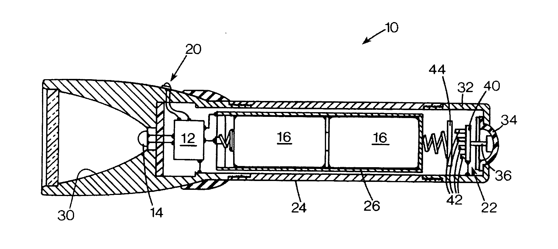
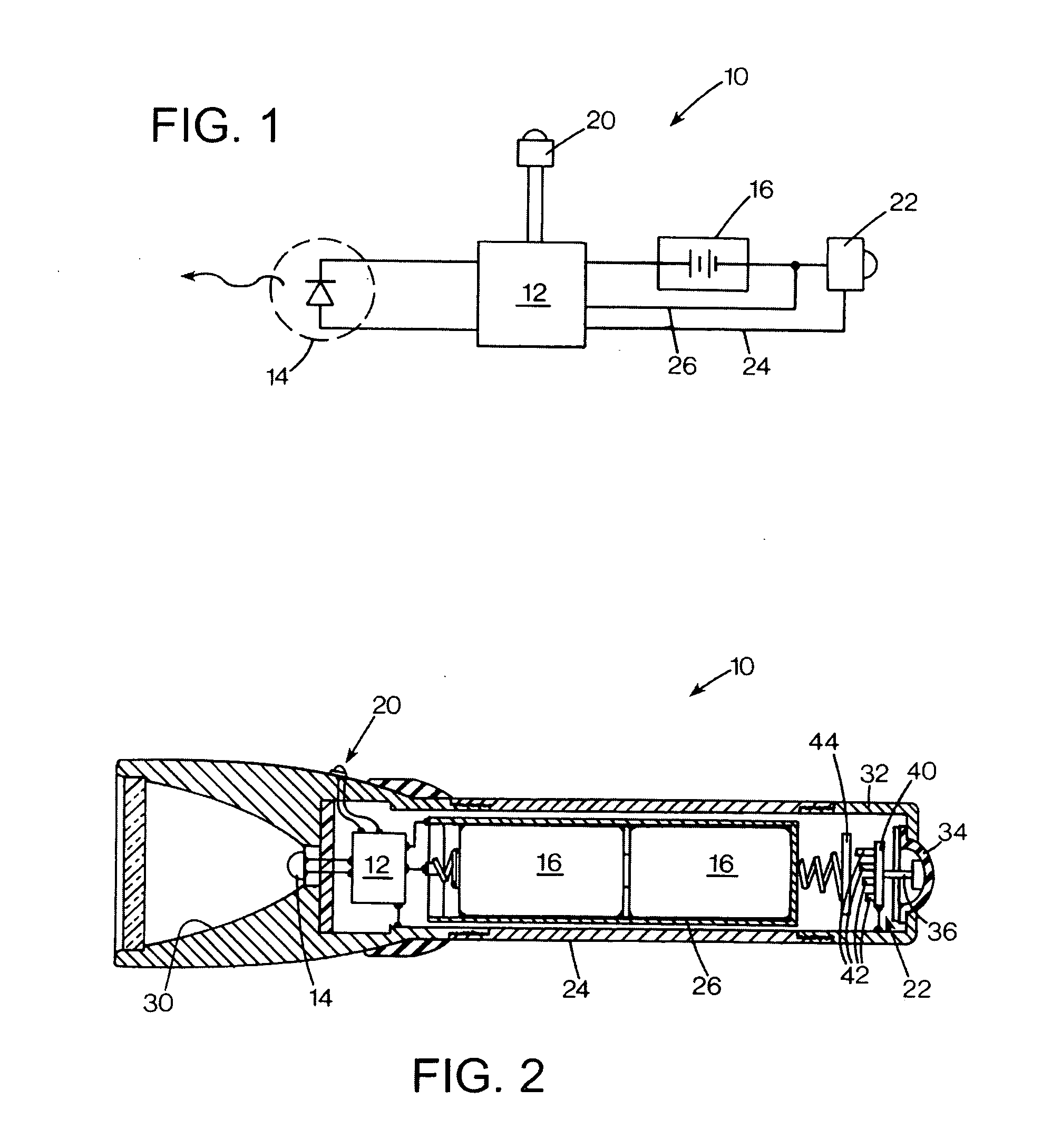
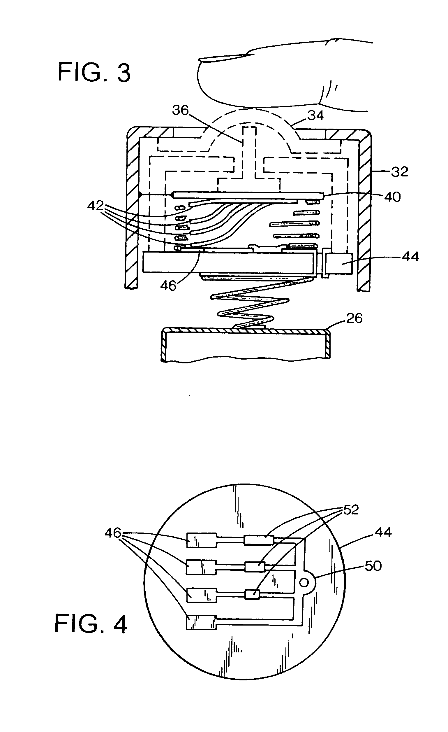
[0021]FIG. 1 shows a schematic drawing of a flashlight 10 according to a preferred embodiment of the invention. The flashlight includes a micro-processor control circuit 12 that is directly connected to a lamp 14, battery 16, dimmed level control selector 20, and operation switch 22.

[0022] The lamp 14 is preferably a light-emitting diode (LED), and may be a single lamp that operates efficiently over a wide range of input power to produce a wide range of possible light outputs. In alternative embodiments, there may be multiple light sources, either interconnected to provide a single, switchable (and dimmable) array, with all sources operating in the same manner. In other alternatives, there may be separate lamps or independently controllable lamp elements, so that color hue changes may be obtained by operating different color components in different combinations, or so that dimming control may be obtained by illuminating a different number of the components. The lamp may be an alter...


PUM


Abstract

A flashlight has a lamp, a power source, two switches, and a controller connected to the switches. The first switch controls delivery of power to the lamp, and the second switch selects a dimmed brightness level. The first switch may invoke the dimmed level, or a maximum brightness level. The second switch may be a ring rotatable about the axis the flashlight, and either rotatable through a wide range of positions, with sensor circuitry to detect the absolute position, or having a limited range of rotation, with dimmed level selection provided by a duration of momentary rotation in either direction. The second switch may be positioned outside a leak resistant housing, and may include a magnet detectable by magnetic field sensors within the chamber.

Description

FIELD OF THE INVENTION [0001] This invention relates to flashlights, and more particularly to switches for controlling flashlight output. BACKGROUND OF THE INVENTION [0002] Flashlights are conveniently sized battery powered portable light sources, which provide the user with a source of illumination. Said illumination could be white light or light of a specific color, or even light outside the visible range of wavelengths, such as ultra violet or infrared radiation. The “color” or wave length of the light will depend on the nature of the light source or light sources used in the flashlight. These would typically be either tungsten lamps, ARC lamps, light emitting diodes (LEDs), lasers, or any other emitter. [0003] Because of the general nature of flashlights and their wide range of applications, it is very desirable for a flashlight to be able to emit, at the user's direction, different levels of light output, and / or different colors or wavelengths of light. This can be accomplished...

Claims


Application Information

Patent Timeline
Patent Type & Authority Applications(United States)
IPC IPC(8): F21L4/02F21V23/04
CPCF21L4/022F21L4/027F21V23/0414F21V23/0421Y10S362/802F21Y2113/005F21Y2113/007H05B33/0803H05B33/0848F21Y2101/02F21Y2115/10F21Y2113/13F21Y2113/17H05B45/14H05B45/30
Inventor MATTHEWS, JOHN W.KIM, PAUL Y.HUNT, WILLIAM A.
Owner SUREFIRE LLC
Why Eureka
Try Eureka