

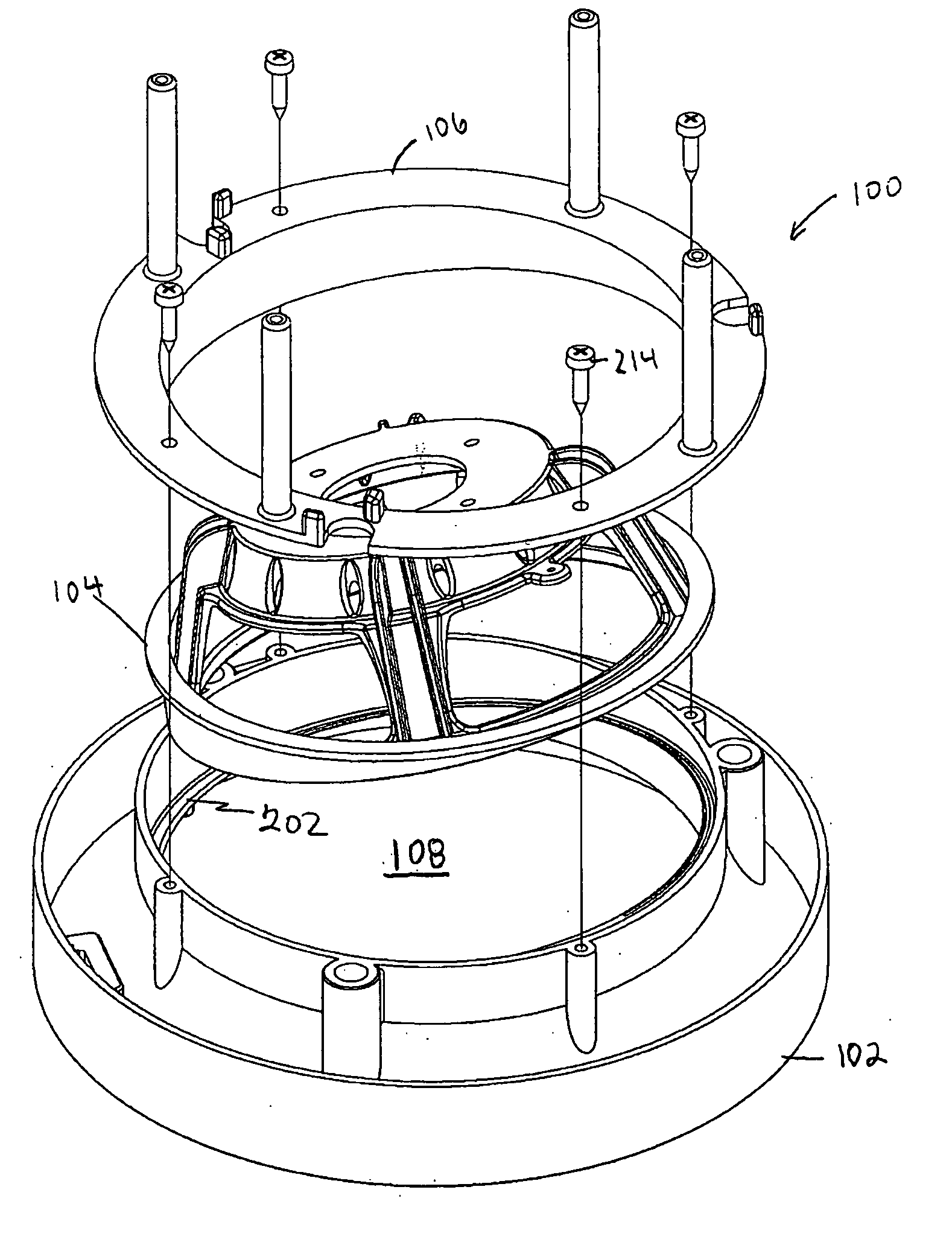
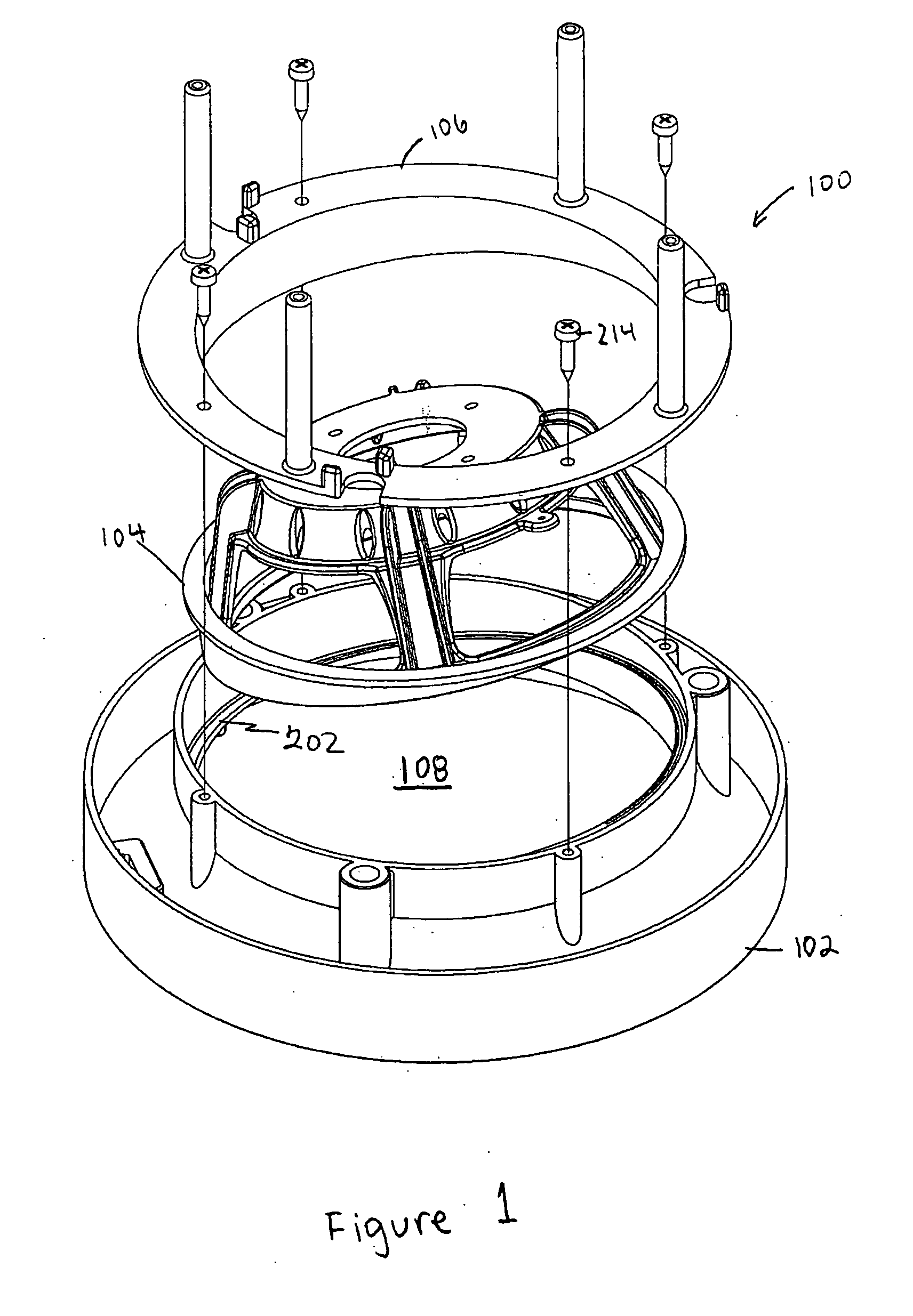
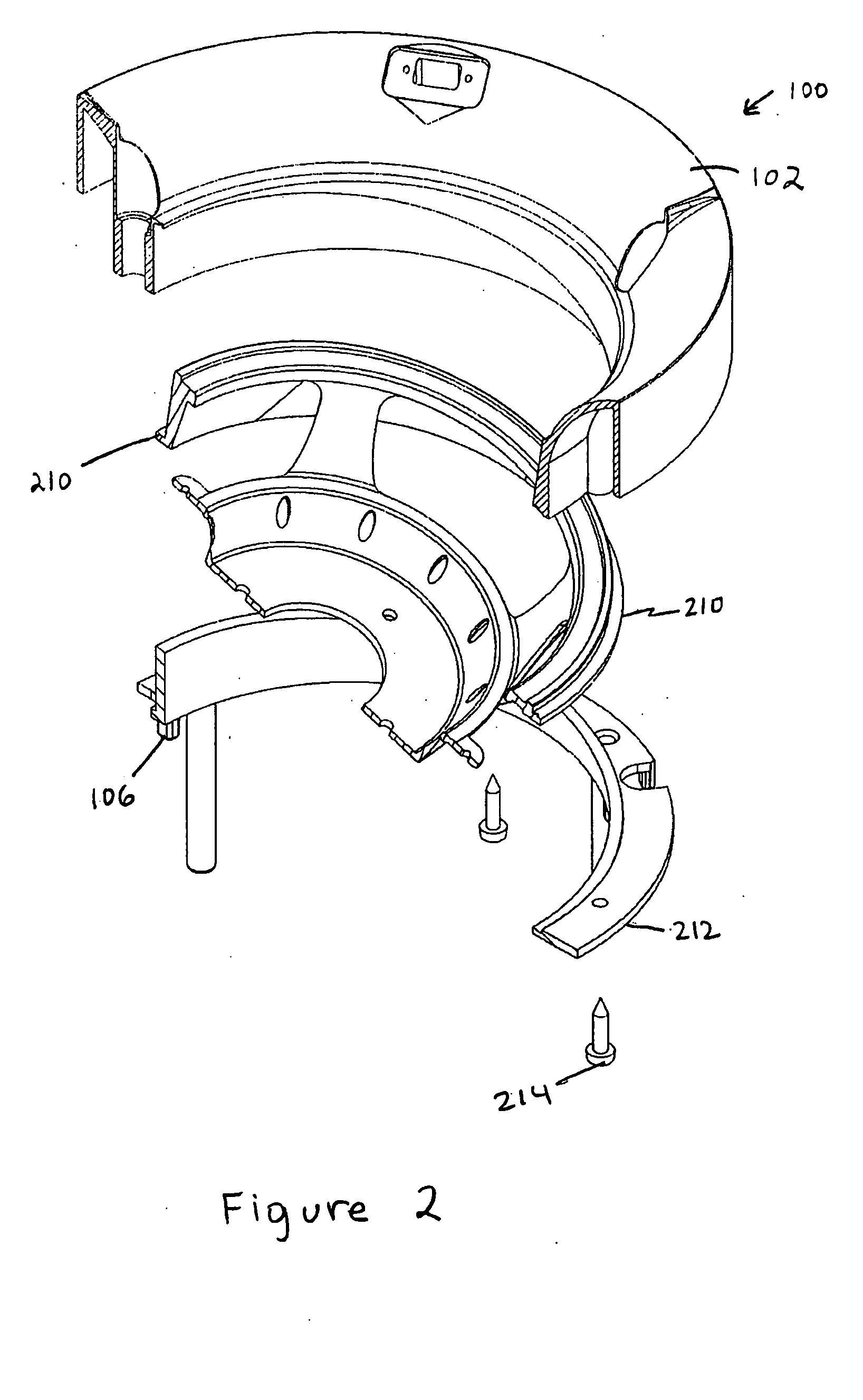
Audio device post extension and angling system
a technology of extension and angling system, applied in the direction of transducer details, electrical transducers, electrical apparatus, etc., can solve the problems of difficult to adjust the sound dispersion axis of speakers, such as the mounting of such audio devices within recessed cavities, and achieve the effect of reducing time and effor
- Summary
- Abstract
- Description
- Claims
- Application Information
AI Technical Summary
Benefits of technology
Problems solved by technology
Method used
Image

Examples
Embodiment Construction
[0037] In the following description numerous specific details are set forth in order to provide a thorough understanding of the invention. However, one skilled in the art would recognize that the invention may be practiced without these specific details. In other instances, well known methods, procedures, and / or components have not been described in detail so as not to unnecessarily obscure aspects of the invention.
[0038] In the following description, certain terminology is used to describe certain features of one or more embodiments of the invention. For instance, “fastener” and “retainer” are interchangeably used to refer to any type of securing mechanism. The term “audio device” is used to refer to any type of sound-generating device, including a speaker, loudspeaker, audio speaker, woofer, subwoofer, tweeter, and / or acoustic transducer. The term “manually” refers to a motion or task performed by hand and without the aid of a tool. The terms “telescoping”, “extendable”, and “adj...
PUM
 Abstract
Description
Claims
Application Information