
Combination anchor bolt holder and concrete form spacer/tie

Inactive Publication Date: 2012-03-20
JONES PAUL
View PDF13 Cites 14 Cited by
  • Summary
  • Abstract
  • Description
  • Claims
  • Application Information

AI Technical Summary

Benefits of technology

[0019]Accordingly, it is an objective of this invention to provide an inexpensive, hardy, reusable anchor bolt holder that, once the cement has cured, can easily be removed and prepared for a reuse with a minimal time and effort.
[0020]Another object of the invention is to provide an anchor bolt holder that holds an anchor bolt stably in a fixed vertical position and at a fixed distance from a side wall of a stem wall foundation while holding a threaded end of the bolt at a predetermined height above a top surface of the cement, and, does so while protecting the threads from a fouling by a cement material during a pouring and finishing process.
[0021]Another object of this invention is to provide an anchor bolt holder that can be used to provide an alignment and holding of a pair of form boards at a separation that will yield a selected width of stem wall, and, does not interfere with a placement of lateral form support bracing being placed at the lateral ends of the bolt holder; and further allowing of a rotational displacement of the holder that allows of a removal of the device from the bolt after an adequate cure level of the cement has occurred so that a fine finishing can be done around a top surface of the stem wall and the bolt projecting above same.

Problems solved by technology

Hartley fails to teach: 1. a feature protecting the threads of the bolts from being fouled by cement during pouring; 2. he also fails to teach a provision for automatically insuring that the anchor bolt is held at a required minimum depth into the concrete with an adequate level of thread for an engagement of the washer and nut that are to be placed on the anchor bolt threads atop the sill plate for the superstructure; 3. he also fails to provide a means for aligning the anchor bolt more centrally within the width of a 2.times.6 sill plate; 4. his device interferes with placing angulated lateral form support braces to reinforce the side walls against the weight of the cement in the form.
The downward projections of Hartley's device would require additional labor for cleaning off accreted cement from the projections once the device is withdrawn from the set concrete.

Method used


Image

  • Combination anchor bolt holder and concrete form spacer/tie
  • Combination anchor bolt holder and concrete form spacer/tie
  • Combination anchor bolt holder and concrete form spacer/tie

Examples


Embodiment Construction

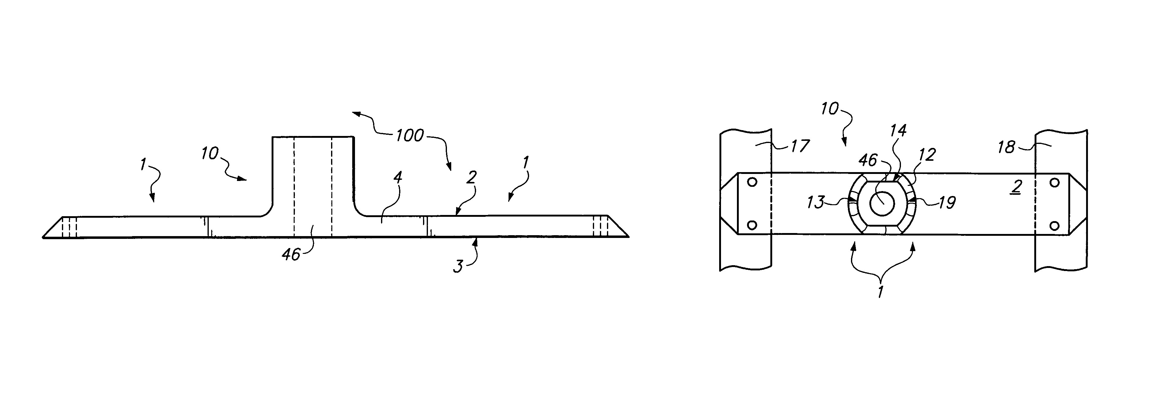
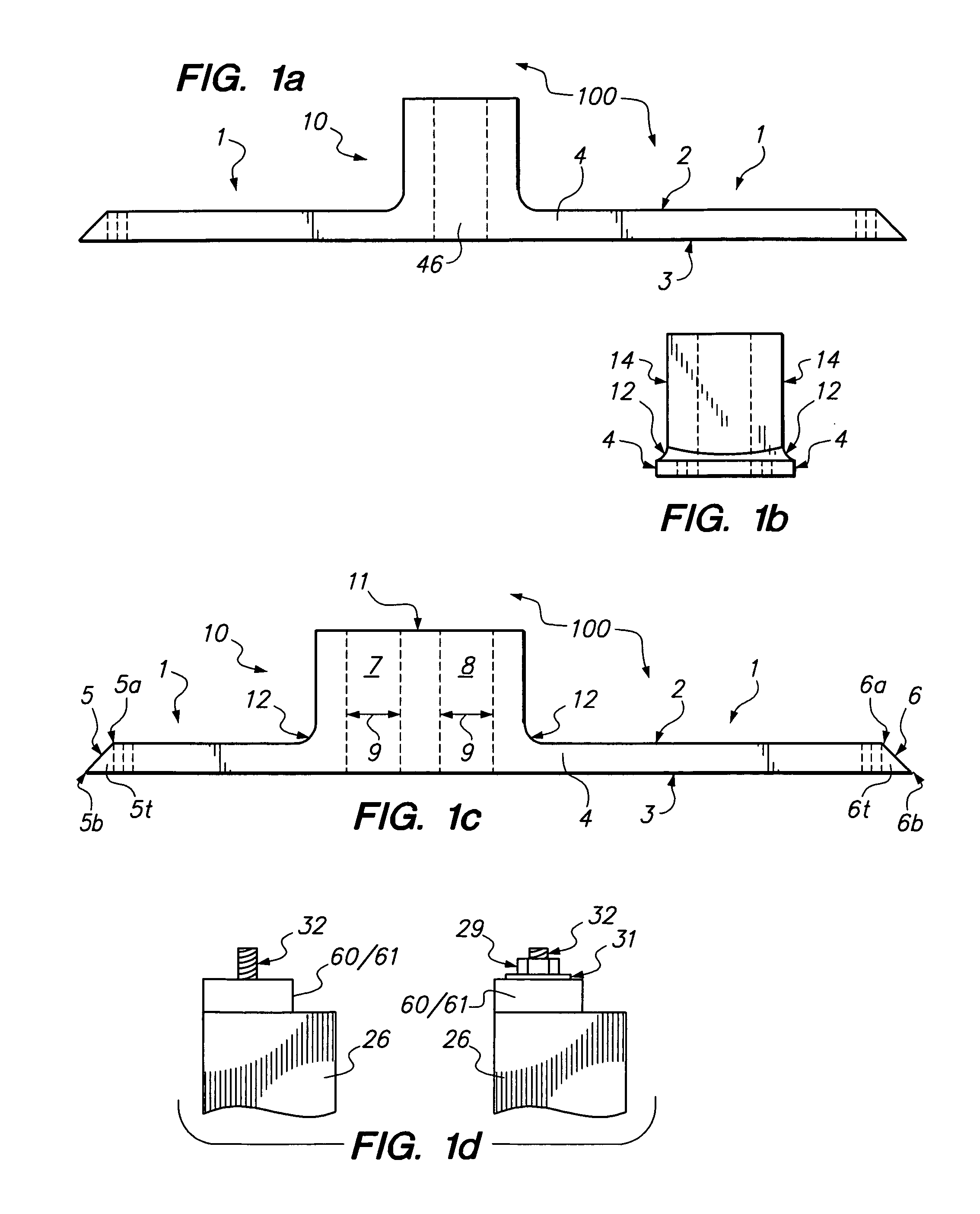
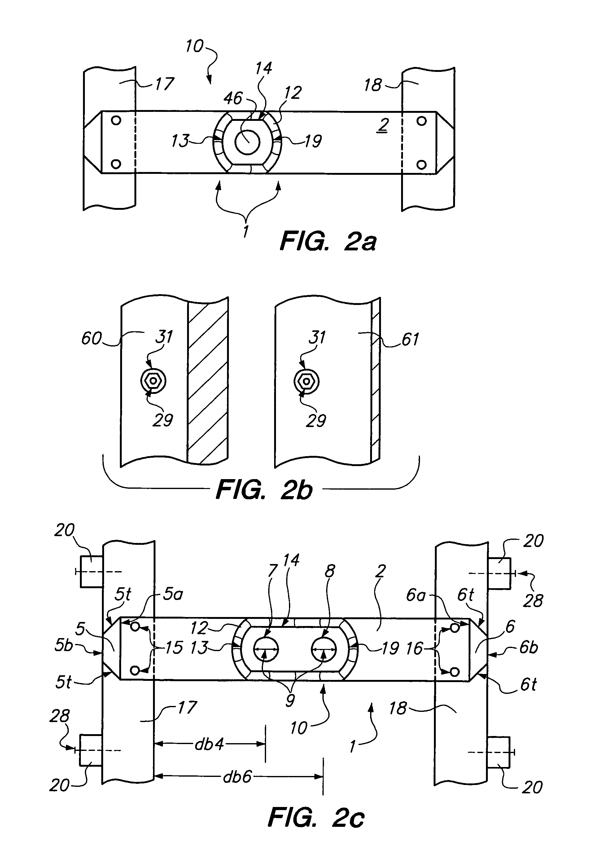
[0053]The improvement, comprises a combination anchor bolt holder, form board internal distance separation alignment and retention, and, thread protection device (“Device”) 100FIG. 1c; said Device comprising in part, at least one vertically oriented bolt hole for a retention of an anchor bolt (aka a J bolt) 200FIG. 3a / 3b, said anchor bolt having a threaded upper end 32FIG. 1d and a non threaded bottom end 33FIGS. 3a / 5a.

Bolt Holder Function

[0054]The Device 100FIG. 1c further comprises in part a unitary combination of a horizontally aligned base portion 1FIG. 1c and an essentially vertically oriented body portion 10FIG. 1c; said base portion 1 comprises in part a shorter, horizontally aligned top surface 2FIG. 1c and a longer, bottom surface 3FIG. 1c; said bottom surface partially comprising an outer-most end termination 5b FIG. 1c and an inner-most end termination 6b FIG. 1c; said base section 1 further comprising in part a pair of vertically aligned, opposed base section side walls...


PUM


Abstract

The invention comprises a reusable, combination—anchor bolt holder, form board alignment and retention, and, thread protection device—for holding an anchor bolt in a secure vertical alignment at an exact depth in the form for either a 2×4 or 2×6 sill plate with the threads fully protected from fouling by cement; and, allowing of early hand float finishing around the bolt thread area that projects above the top of the stem wall.

Description

BACKGROUND OF THE INVENTION[0001]1. Field of the Invention[0002]The invention relates to a template for setting anchor bolts in concrete foundations; more particularly it relates to a reusable device that allows of a visual alignment of an internal top edge of each of a pair of form boards at an appropriate distance of internal separation and also provides an ability for a tieing into place of the tops of the form boards while simultaneously providing a support for holding an anchor bolt in an appropriate position within the stem wall form for a passage of an appropriate length of a threaded superior end of the anchor bolt in an upwards projection above a top surface of the stem wall and as well as through a hole in either a nominal 2.times.4 or a nominal 2.times.6 sill plate as well as a passage through and above an anchor bolt washer and nut, and, does so with a threaded end of the anchor bolt being afforded a protection against being fouled with cement and with a non-threaded bas...

Claims


Application Information

Patent Timeline
IPC IPC(8): G01B5/24
CPCG01B5/14G01B5/24
Inventor JONES, PAUL
Owner JONES PAUL
Learn More