Shifter for a bicycle transmission

a technology of shifting and bicycles, applied in the direction of mechanical control devices, limiting/preventing/returning movement of parts, controlling members, etc., can solve the problems of sluggishness, shifters that produce loud shifting noises, and are sensitive to tolerances and demands in terms of manufacture and space requirements, and achieve economic manufacturing

Inactive Publication Date: 2005-06-16
SRAM
View PDF3 Cites 23 Cited by
  • Summary
  • Abstract
  • Description
  • Claims
  • Application Information

AI Technical Summary

Benefits of technology

[0006] An object of the present invention is to provide a shifter having shifting components that can be economically manufactured and are both suitable for both lever shifters and twistshifters.
[0007] The present invention provides a shifter for a bicycle transmission. The shifter generally includes a housing, an actuator, a cable spool, a locking pawl and retaining and releasing elements. The housing is mounted to a handlebar. The actuator is operated by the rider to select a desired gear ratio. The actuator is connected to the housing via a mandrel. The cable spool includes a tab that rotatably connects the cable spool to the actuator. The releasing element is nonrotatably connected to the actuator and the retaining element is nonrotatably connected to the cable spool. The releasing element includes a releasing contour having a plurality of releasing teeth. The retaining element includes a retaining contour having a plurality of retaining teeth. The locking pawl holds the desired gear ratio. The locking pawl has first and second ends. The first end of the locking pawl is supported in the housing. The second end of the locking pawl simultaneously engages the retaining and releasing contours and may be biased toward the retaining element. In one embodiment of the present invention, the locking pawl is a spring supported by the housing near the cable guide for the control cable. This configuration minimizes the outer diameter of the housing which is especially favorable for twistshifters.
[0008] The retaining element may be a disk having a retaining contour on its periphery. Alternatively, the retaining element and the cable spool may form one part. The releasing element may also be a disk having a releasing contour on its periphery. Alternatively, the releasing element and the actuator may form one part. The elevations of the retaining contours form retaining teeth having retaining edges and the elevations of the releasing contour form releasing teeth having saw-tooth shapes. Each retaining tooth corresponds to a releasing tooth. The spacing between the retaining teeth corresponds to a gear ratio and the necessary control cable displacement for each gear change. The configuration of the releasing teeth, in particular the tooth flank facing in the releasing direction, provides a desired releasing profile that substantially influences shifting sensitivity. The releasing profile of the tooth flank of the releasing teeth can have a straight, convex, concave or any other type profile sufficient to move the locking pawl out of locked engagement with the retaining tooth. In addition to the simple and compact construction, the present invention provides an individual release travel and release force for each gear ratio because of the various shapes of the releasing teeth.
[0010] In another embodiment, a preload spring is arranged between the actuator and the cable spool to assist the release operation and to prevent any play between the actuator and the cable spool. The preload spring may be a compression spring received in a slot in one of the cable spool and the actuator. One end of the preload spring is braced against an end of the slot and another end of the preload spring is braced against a tab that extends from one of the actuator and cable spool. Another end of the slot also serves a stop for the tab that the preload spring acts on.
[0012] During the cable-pull operation, the rotational movement of the actuator or rotatable grip is transferred directly to the cable spool via at least one drive element extending from the actuator to the cable spool. The locking pawl slides over the retaining teeth and the corresponding releasing tooth. At the end of the cable-pull operation, the locking pawl ratchets into the next tooth gap of the retaining contour and braces itself once again against the corresponding retaining edge of the next retaining tooth. The cable spool or tensioned control cable thus travels a defined shifting distance. If the actuator is moved further, it is thus also possible to shift through several gears in succession with one actuation, the ratcheting of the locking pawl into place indicating that a new gear ratio has been reached.
[0014] The prevent invention allows its components, in particular the cable spool, retaining element, releasing element and the actuator, to be arranged around a central axis. This configuration permits a very compact design that is suitable for both lever shifters and twistshifters.

Problems solved by technology

The shifters disclosed in the above-mentioned patent applications are functional but are sluggish, sensitive to tolerances and demanding in terms of manufacture and space requirements.
Further, the shifters produce loud shifting noises.

Method used


Image

  • Shifter for a bicycle transmission
  • Shifter for a bicycle transmission
  • Shifter for a bicycle transmission

Examples


Embodiment Construction

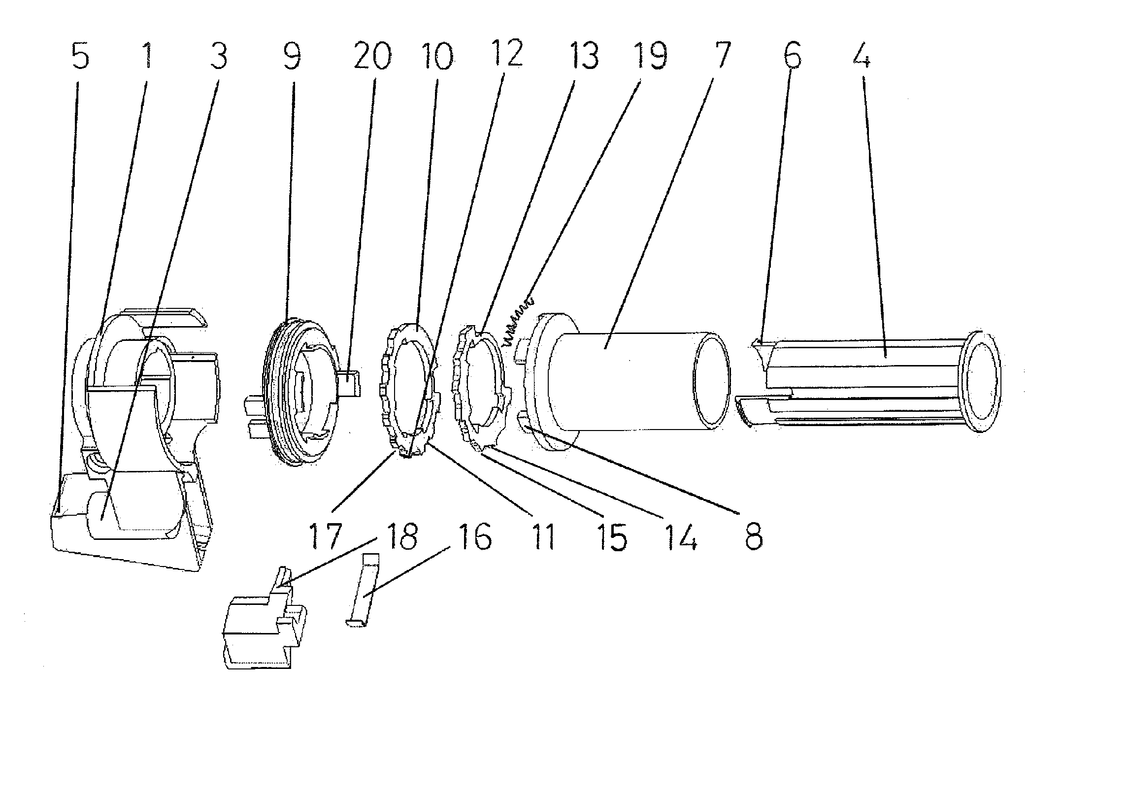
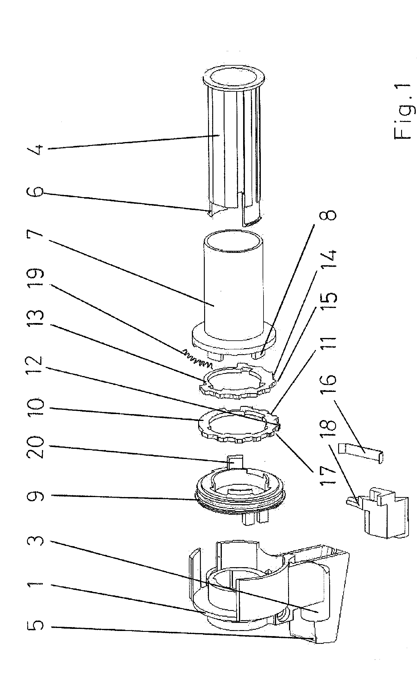
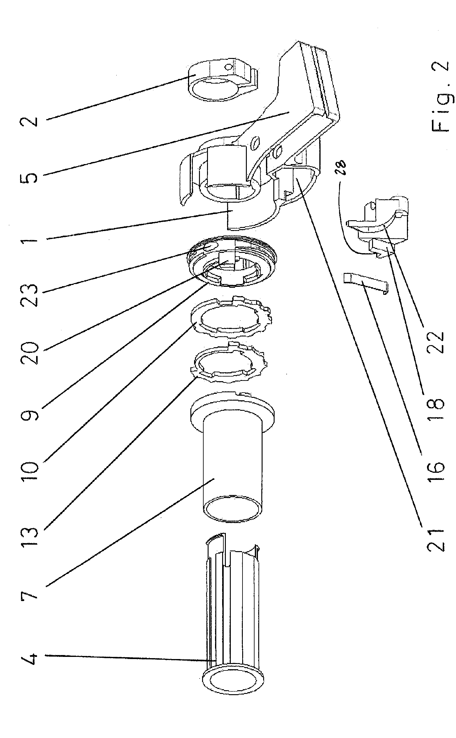
[0021]FIGS. 1-4 illustrate a bicycle shifter in accordance with one embodiment of the present invention. The shifter generally includes a housing 1, an actuator 7, a retaining element 12, a releasing element 13, a locking pawl 16 and a cable spool 9. Looking to FIG. 1, the housing 1 includes an integrated handlebar clamp 2, a cable guide portion 3 for receiving a control cable (not shown) and a brake housing portion 5. The actuator 7 is mounted over a mandrel 4 that includes two elastic retaining fingers 6 that snap into the housing 1. The actuator 7 is rotatable in a cable-pull direction and a cable-release direction opposite the cable-pull direction. The actuator 7 includes at least one drive element 8 engageable with the cable spool 9 to transfer the shifting motion in the cable-pull direction to the cable spool. Alternatively, the drive element 8 may be located on the cable spool 9. The retaining element 10 is nonrotatably connected to the cable spool 9 and includes a retaining ...


PUM


Abstract

A shifter for a bicycle transmission that includes a housing, a cable spool, an actuator, a locking pawl simultaneously engageable with teeth of a releasing element and a retaining element. A cable-release operation is initiated by motion of the releasing element relative to the retaining element which causes the releasing teeth to slide under the locking pawl and lift the locking pawl over a retaining tooth. A preload spring is arranged between the actuator and the cable spool to prevent play between the actuator and the cable spool and is also preloaded during the cable-release operation to assist the cable-release operation after the locking pawl is released from the retaining teeth.

Description

[0001] The present invention relates to bicycle shifters and more particularly to a bicycle shifter that includes a locking pawl that simultaneously engages a retaining contour and a releasing contour. [0002] Bicycle shifters are used to pull and release a tensioned control cable connected to a gear change mechanism and to hold the desired gear ratio. These types of shifters are disclosed in the German patent applications DE 1 99 18 520 A1 and DE 1 033 063. These shifters generally include an actuator and a cable spool for pulling and releasing cable and a retaining device for holding the tensioned control cable in a particular position. The actuator rotates the cable spool, while the retaining device continuously holds the cable spool in a current shift position and thus counteracts the return force of the tensioned control cable. [0003] DE 1 99 18 520 A1 discloses a shifter including a rotatable actuator nonrotatably connected to the cable spool having a locking pawl that engages ...

Claims


Application Information

Patent Timeline
Patent Type & Authority Applications(United States)
IPC IPC(8): G05G1/08G05G5/06
CPCG05G1/08Y10T74/2042G05G5/06
Inventor BLASCHKE, GEORG
Owner SRAM
Why Eureka
Try Eureka