Method for detecting an obstacle around a vehicle

a detection device and obstacle technology, applied in the direction of measurement devices, vehicle components, instruments, etc., can solve the problems of inability to obtain reflected waves sufficient for distance detection from the cut-in vehicle, the device becomes incapable of detecting the distance to (lost track of) the vehicle ahead, and the problem of affecting the detection effect of the device, etc., to achieve the effect of judging the detection capability of the device with accuracy

Active Publication Date: 2005-06-16
DENSO CORP
View PDF14 Cites 19 Cited by
  • Summary
  • Abstract
  • Description
  • Claims
  • Application Information

AI Technical Summary

Benefits of technology

[0011] Thus, even if any vehicle (a cut-in vehicle) or object is present on this side of a vehicle ahead in reality and is undetectable because of dirt on it or the non-reflectiveness of it, there is no problem. As long as the signal level of reflected waves from the vehicle ahead is equal to or above a preset signal level, the distance to the vehicle ahead is prevented from being judged as a sight start distance or sight end distance. As a result, the detecting capability of the device can be judged with accuracy.

Problems solved by technology

The device acquires a distance at which the device becomes incapable of detecting the distance to (lose track of) the vehicle ahead (sight end distance).
If there is a cut-in vehicle between a vehicle ahead to which the sight end distance is to be detected and the vehicle of interest, a problem arises.
The vehicle ahead is hidden behind the cut-in vehicle and cannot be detected (creation of blind spot).
However, this poses a problem.
There is a case where a cut-in vehicle is actually present between a vehicle ahead and the vehicle of interest but reflected waves sufficient for distance detection cannot be obtained from the cut-in vehicle because of, for example, dirt on the rear part of the cut-in vehicle.

Method used


Image

  • Method for detecting an obstacle around a vehicle
  • Method for detecting an obstacle around a vehicle
  • Method for detecting an obstacle around a vehicle

Examples


Embodiment Construction

[0030] Referring to the drawings, the obstacle detection device for vehicle in the embodiment of the present invention will be described below. In this embodiment, the obstacle to be detected is a vehicle ahead, and detecting capability judgment is made on the obstacle detection device for vehicle based on detection data from the vehicle ahead.

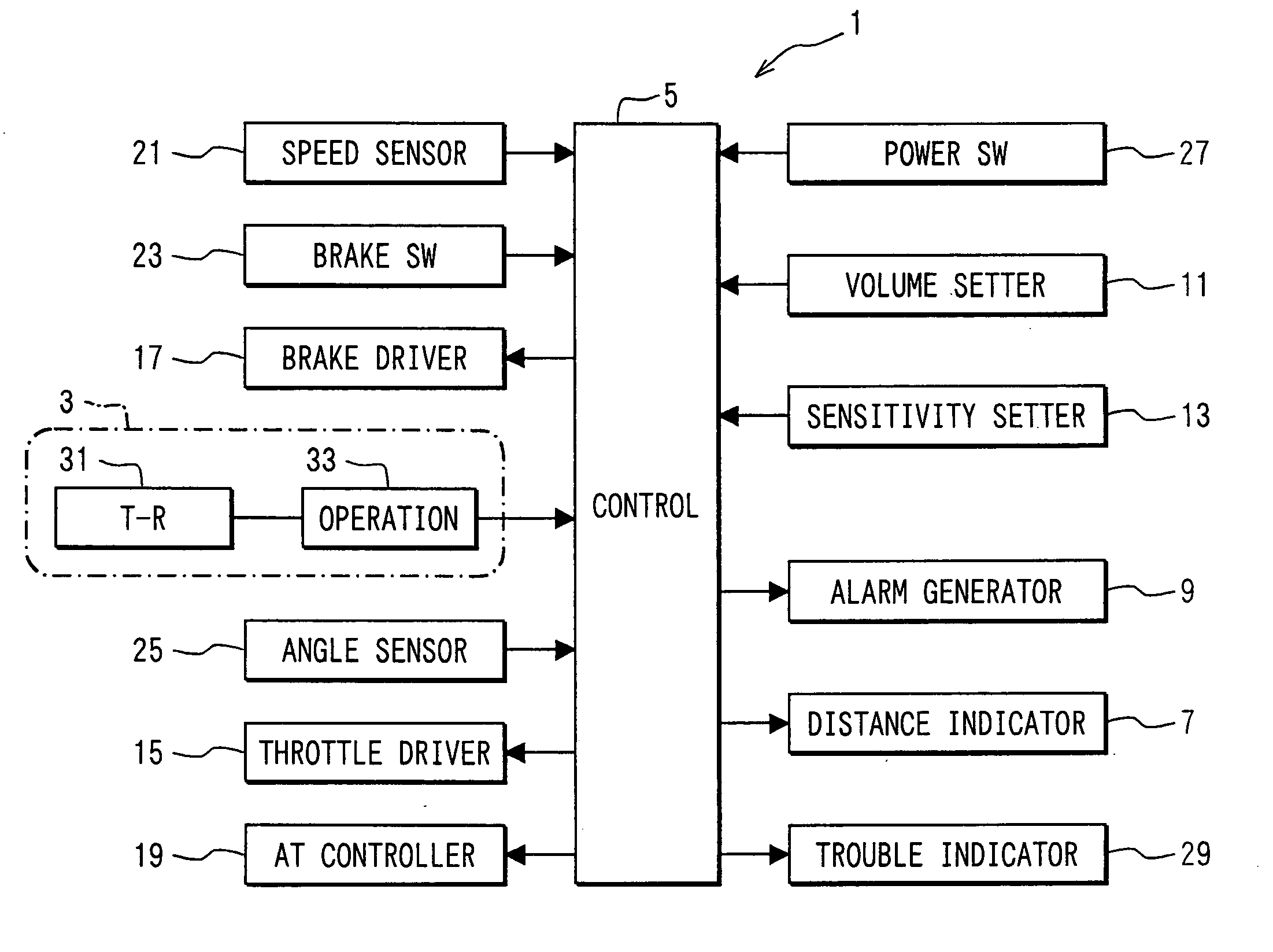
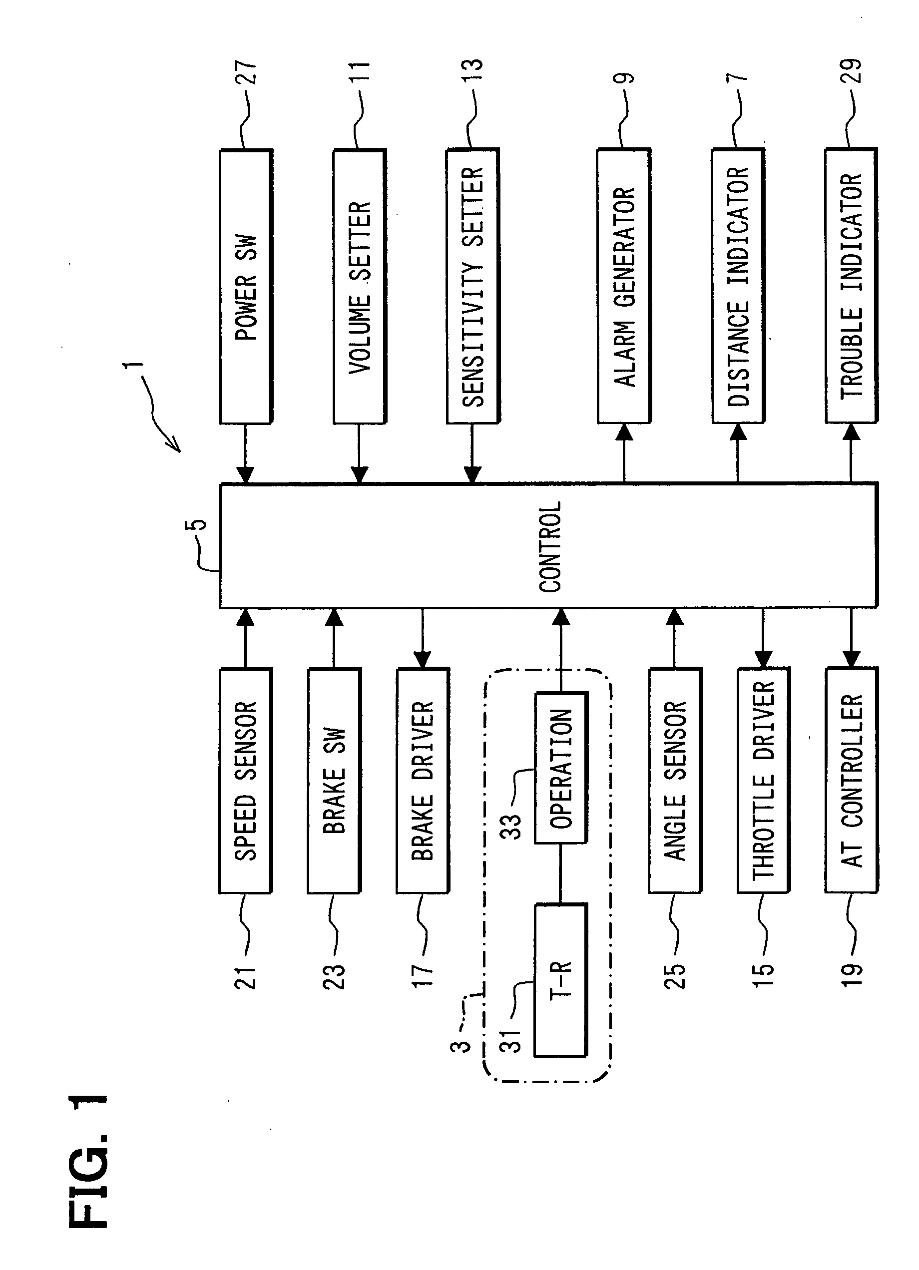
[0031]FIG. 1 illustrates the constitution of a vehicle controller to which the obstacle detection device for vehicle in this embodiment is applied. As illustrated in the figure, the vehicle controller 1 detects any vehicle ahead by the scanning distance measuring equipment 3 as a radar means. The vehicle controller 1 performs either or both of two different types of control according to the setting of a mode switch (not shown): rear end collision preventive control and tailing cruising control (following distance control). Under rear end collision preventive control, an audible alarm is generated when the vehicle ahead gets in a predetermined...


PUM


Abstract

If the maximum time width Lt of the intensity of received light of reflected waves from a vehicle ahead is smaller than a reference time width, it is judged that the vehicle ahead is positioned in proximity to the detection limit distance of an obstacle detection device for vehicle. Thus, there is no problem, for example, even if a cut-in vehicle is present in reality between the vehicle ahead and the vehicle of interest and nevertheless, the distance to the cut-in vehicle cannot be detected. It can be judged whether the vehicle ahead is positioned in proximity to the detection limit distance of the device by judging the magnitude relation between Lt and the reference time width. As a result, the detecting capability of the device can be judged with accuracy.

Description

CROSS REFERENCE TO RELATED APPLICATIONS [0001] This application is based on and incorporates herein by reference Japanese Patent Application No. 2002-348701 filed on Nov. 29, 2002. FIELD OF THE INVENTION [0002] The present invention relates to an obstacle detection device for vehicle. BACKGROUND OF THE INVENTION [0003] Conventionally, there have been various obstacle detection devices for vehicle which detect obstacles around a vehicle. Among them is one that self-diagnoses the detecting capability of the device itself without any inspecting device additionally installed (refer to Patent Document 1: JP-A-11-94946 (U.S. Pat. No. 6,147,637), for example). In detecting capability judgment processing by the obstacle detection device for vehicle disclosed in Patent Document 1, judgment is made as follows: for example, a vehicle ahead (or preceding vehicle) is driving away from a vehicle of interest. The device acquires a distance at which the device becomes incapable of detecting the dis...

Claims


Application Information

Patent Timeline
Patent Type & Authority Applications(United States)
IPC IPC(8): G01S17/931G08G1/16B60R21/00
CPCG01S17/936G01S17/931
Inventor SAMUKAWA, YOSHIEMATSUOKA, KEIJIOOKATA, HIROSHINOZAWA, TOYOHITO
Owner DENSO CORP
Why Eureka
Try Eureka