Fuel injection valve and manufacturing method thereof

a technology of fuel injection valve and manufacturing method, which is applied in the direction of machines/engines, soldering devices, applications, etc., can solve the problem of not being able to obtain the desired flow rate of fuel injected from the fuel injection valv

Inactive Publication Date: 2009-04-30
MITSUBISHI ELECTRIC CORP
View PDF0 Cites 10 Cited by
  • Summary
  • Abstract
  • Description
  • Claims
  • Application Information

AI Technical Summary

Benefits of technology

[0006]Accordingly, the present invention is intended to obviate the problem as referred to above, and has for its object to provide a fuel injection valve and a manufacturing method thereof in which upon mounting of the fuel injection valve

Problems solved by technology

As a result, there has been a problem that it is impossible to obtai

Method used


Image

  • Fuel injection valve and manufacturing method thereof
  • Fuel injection valve and manufacturing method thereof
  • Fuel injection valve and manufacturing method thereof

Examples


embodiment 1

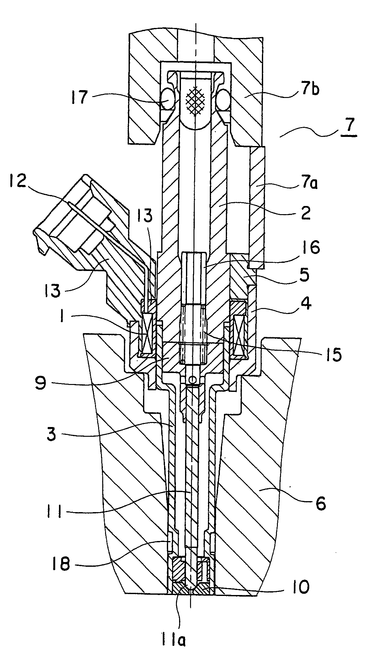
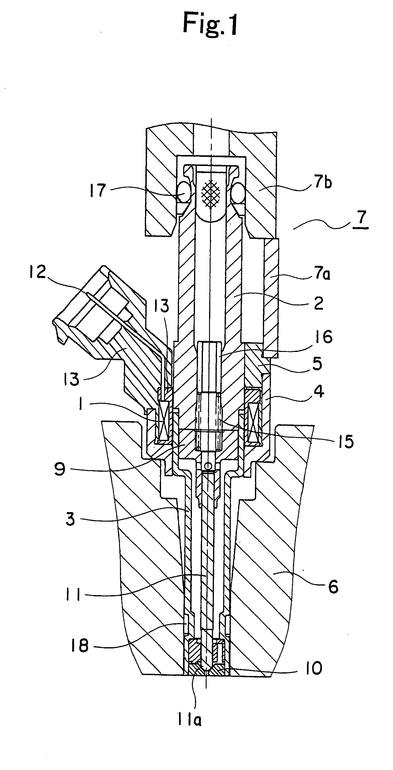
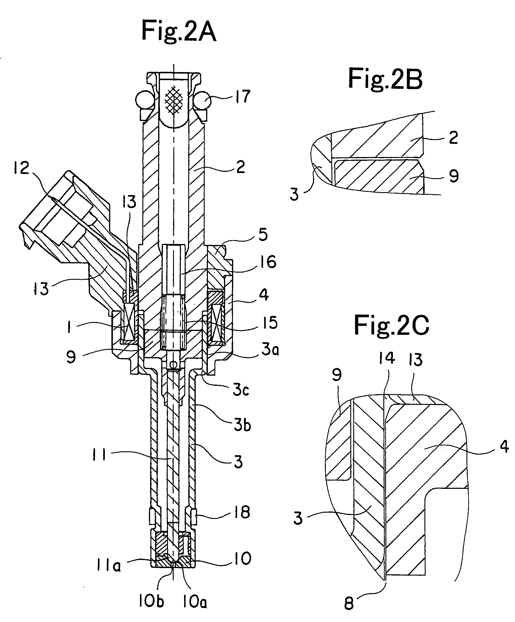
[0032]Referring to the drawings and first to FIG. 1, there is shown, in a cross sectional view, how a fuel injection valve according to a first embodiment of the present invention is mounted on an engine. FIG. 2A is a cross sectional view of the fuel injection valve in FIG. 1. FIG. 2B is an enlarged view that shows the relation between a core 2 and an armature 9 in FIG. 2A. FIG. 2C is an enlarged view that shows the relation between a body 3 and a housing 4 in FIG. 2A.

[0033]The fuel injection valve according to this embodiment includes a coil 1 that is adapted to be energized to generate a magnetic field, the core 2 of a cylindrical shape that has one end thereof arranged at an inner side of the coil 1, and the other end thereof through which fuel is supplied to flow thereinto, and the body 3 of a cylindrical shape that has one end thereof fixedly attached to the one end of the core 2, and the other end thereof from which fuel is injected.

[0034]In addition, the fuel injection valve ...

embodiment 2

[0065]FIG. 4A is a cross sectional view that shows a fuel injection valve according to a second embodiment of the present invention. FIG. 4B is an enlarged view that shows the relation between a body 3 and a housing 4 in FIG. 4A.

[0066]In the fuel injection valve according to this second embodiment, the housing 4 is formed, at an end portion thereof abutting a cylinder head 6, with a protruded portion 4a that protrudes to a diametrically inner side. The protruded portion 4a is able to be in abutment with a stepped portion 3c of the body 3.

[0067]In case where the fixed connection of a core 2 and a cap 5 is released, even if the core 2 and the body 3 are subjected to a force acting thereon in a direction toward a cylinder head 6 (refer to FIG. 1) under the pressure of fuel in the interiors of the core 2 and the body 3, the protruded portion 4a serves to restrict the movement of the body 3 toward the cylinder head 6, so it is possible to prevent the fuel from leaking from between the co...

embodiment 3

[0070]FIG. 5A is a cross sectional view that shows a fuel injection valve according to a third embodiment of the present invention. FIG. 5B is an enlarged view that shows a cap 5 in FIG. 5A. FIG. 5C is a view that shows a state that the fuel injection valve in FIG. 5A is mounted on an engine.

[0071]In the fuel injection valve according to this third embodiment, the cap 5 has a portion 5a of a thin thickness formed at an end portion thereof near a fastening unit 7.

[0072]Thus, the thin thickness portion 5a is able to be deformed in a diametrical direction, so when the fuel injection valve is mounted on the engine with a cylinder head 6 and a common rail 7b being arranged in an eccentric manner, the core 2 and the body 3 can be inclined, as a result of which a force applied to an O ring 17 and a side seal 18 can be reduced, thereby making it possible to improve sealing performance of the O ring 17 and the side seal 18.

[0073]The construction of this third embodiment other than the above ...


PUM

PropertyMeasurementUnit
Thicknessaaaaaaaaaa
Diameteraaaaaaaaaa
Distanceaaaaaaaaaa

Abstract

When a fuel injection valve is mounted on an engine, a distance between a core and an armature during non-energization of a coil can be prevented from becoming narrow. The coil is arranged inside the core, and a body is fixedly secured at its one end to an end of the core. A housing is arranged outside the coil with its one end abutting a cylinder head. A cap is arranged at the other end of the housing, and abuts at its side opposite to the housing with a fastening unit. The armature is arranged for reciprocation inside the body, and is magnetically attracted to the magnetized core. A gap is formed between the housing and the body, with the cap and the core being fixed to each other, and upon mounting the valve on the engine, the housing and the fastening unit abut the cylinder head and the cap, respectively.

Description

BACKGROUND OF THE INVENTION[0001]1. Field of the Invention[0002]The present invention relates to a fuel injection valve which includes a coil, a core having an end thereof arranged at an inner side of the coil, a body having an end thereof fixedly secured to the end of the core at an inner side of the coil, and an armature arranged at an inner side of the body, and also relates to a method for manufacturing such a fuel injection valve.[0003]2. Description of the Related Art[0004]In the past, there has been known a fuel injection valve which includes: a coil that is adapted to be energized to generate a magnetic field; a core that has an end arranged at an inner side of the coil and is magnetized by the magnetic field generated by the coil; a cylindrical body that is made of a magnetic material, has an end thereof fixedly attached to the end of the core at an inner side of the coil, and is arranged so as to cover an axial end portion of the coil and in abutment with a cylinder head o...

Claims


Application Information

Patent Timeline
IPC IPC(8): F02M51/06
CPCF02M61/168Y10T29/49314Y10T29/49405F02M51/0653
Inventor KITAGAWA, KAZUNORIOJIMA, KOUICHIONISHI, YOSHIHIKO
Owner MITSUBISHI ELECTRIC CORP
Why Eureka
Try Eureka