
Frame structure in motorcycle

Inactive Publication Date: 2007-09-11
HONDA MOTOR CO LTD
View PDF33 Cites 15 Cited by
  • Summary
  • Abstract
  • Description
  • Claims
  • Application Information

AI Technical Summary

Benefits of technology

[0008]An object of the present invention is to provide a frame structure in a motorcycle which permits the required bending work to be performed relatively easily.
[0009]An object of the present invention is to provide a frame structure in a motorcycle wherein the distance between lower portions of a pair of right and left pipe members can be made wider and the distance between upper portions of both pipe members can be made relatively narrow.
[0012]In the aforementioned construction, both inner and outer walls of both pipes members are formed substantially in parallel with each other, so that a bending work for both pipe members can be performed relatively easily. Since the pipe members are inclined in this relatively simple structure, it is possible to narrow the distance between upper portions of both pipe members and thereby make it difficult for rider's knees to come into contact with the pipe members and / or the distance between lower portions of both pipe members can be widened to ensure a sufficient engine mounting space.

Problems solved by technology

Therefore, the bent surfaces of the pipe members and their respective side walls are not orthogonal to each other and thus bending of the stock after extrusion is relatively difficult.

Method used


Image

  • Frame structure in motorcycle
  • Frame structure in motorcycle
  • Frame structure in motorcycle

Examples


Embodiment Construction

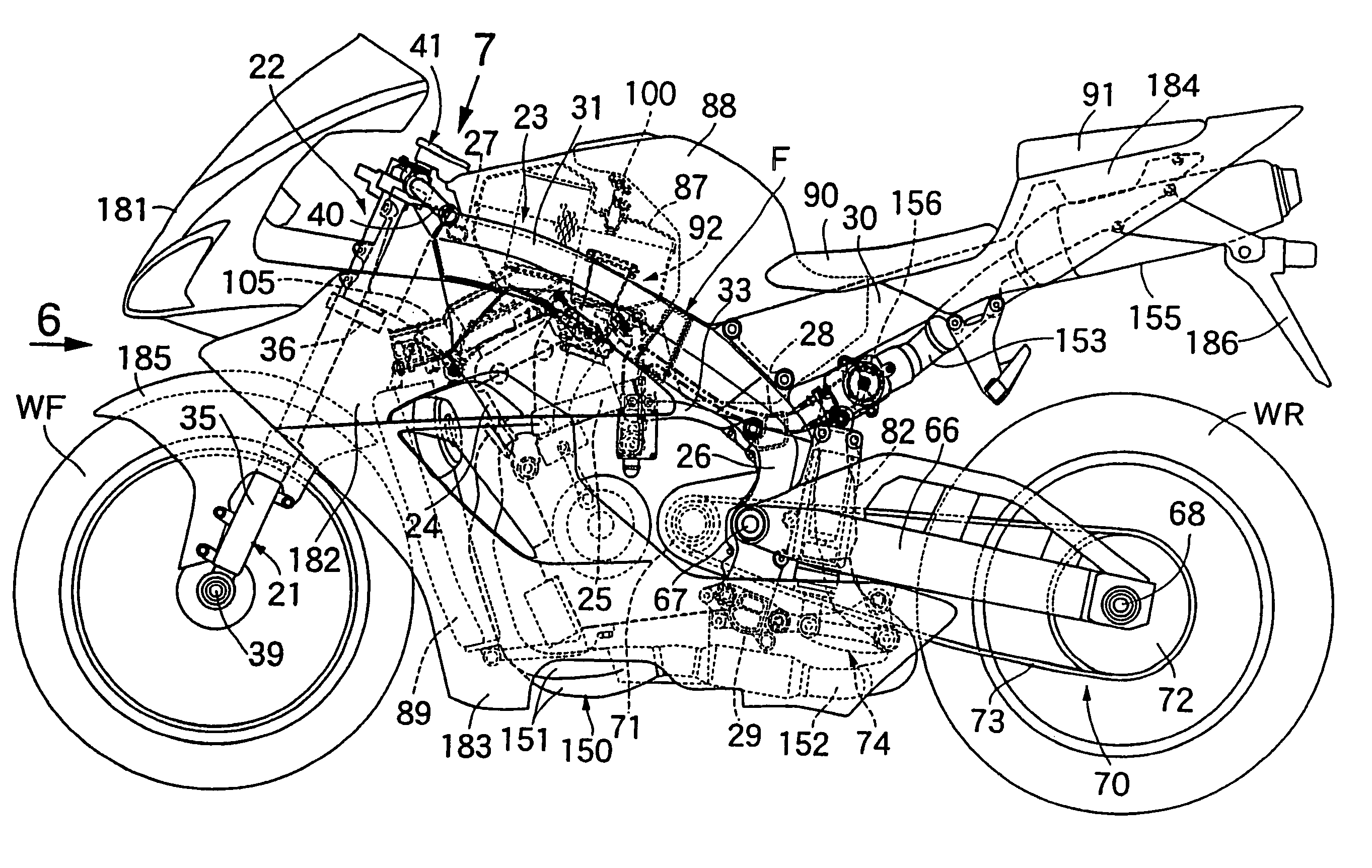
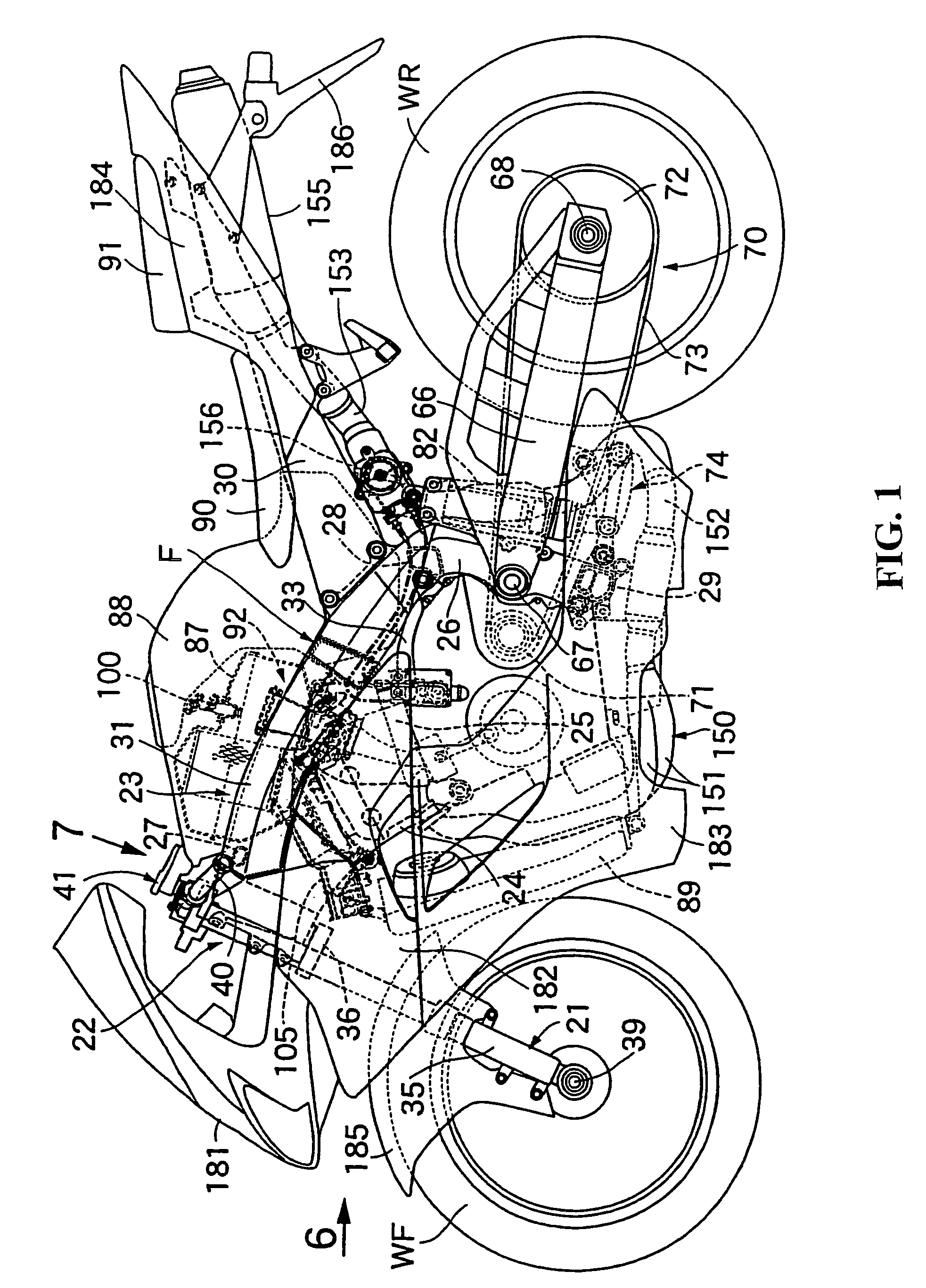
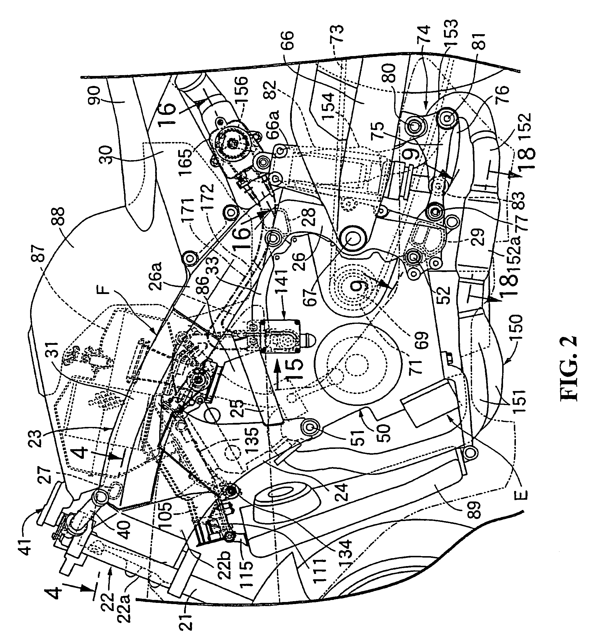
[0034]The present invention will hereinafter be described with reference to the accompanying drawings. FIG. 1 is a side view of a motorcycle according to an embodiment of the present invention. FIG. 2 is an enlarged view of a portion of FIG. 1. FIG. 3 is a plan view of a front portion of a vehicle body frame according to an embodiment of the present invention. FIG. 4 is an enlarged sectional view of the front portion of the vehicle body frame taken along line 4-4 in FIG. 2. FIG. 5 is a sectional view taken along line 5-5 in FIG. 2. FIG. 6 is an enlarged view as seen in the direction of arrow 6 in FIG. 1. FIG. 7 is an enlarged view as seen in the direction of arrow 7 in FIG. 1. FIG. 8 is a sectional view taken along line 8-8 in FIG. 7. FIG. 9 is a sectional view taken along line 9-9 in FIG. 2. FIG. 10 is a sectional view taken along line 10-10 in FIG. 6.

[0035]First, in FIGS. 1 to 3, a body frame F in this motorcycle includes a head pipe 22 which supports a front fork 21 steerably, th...


PUM


Abstract

A frame structure for a motorcycle includes a front fork which journals a front wheel and that is capable of being steered and supported by a head pipe. Front end portions of a pair of right and left pipe members are connected contiguously to the head pipe and extend downwardly and rearwardly from the head pipe. The pair of right and left pipe members each have a substantially prismatic cross sectional shape and are each bent at their longitudinally intermediate portions so as to be outwardly convex with respect to the sides of the motorcycle frame. An engine is disposed between lower portions of both pipe members in an engine mounting space. The present invention narrows the distance between the upper portions of the right and left pipe members and effectively increases the space between the lower portions of the pair of right and left pipe members.

Description

CROSS-REFERENCES TO RELATED APPLICATIONS[0001]This nonprovisional application claims priority under 35 U.S.C. § 119(a) on Patent Application No. 2003-095105 filed in Japan on Mar. 31, 2003, the entirety of which is herein incorporated by reference.BACKGROUND OF THE INVENTION[0002]1. Field of the Invention[0003]The present invention relates to a motorcycle, and more particularly to a motorcycle having front end portions of a pair of right and left pipe members, each front end portion having an external shape of a prismatic cross section and which being bent sideways in an outwardly convex shape at a longitudinally intermediate position. The front end portions are connected contiguously to a head pipe, a front fork which supports a front wheel through a shaft is supported by and steerable by the head pipe, and an engine is disposed between lower portions of both the pipe members. The present invention is also concerned with the improvement of a frame structure for a motorcycle having ...

Claims


Application Information

Patent Timeline
IPC IPC(8): B62D61/02B62K11/00B62M7/00B62K11/04
CPCB62K11/04
Inventor NAGASHII, TOSHIHISAHARIU, JUN
Owner HONDA MOTOR CO LTD
Learn More