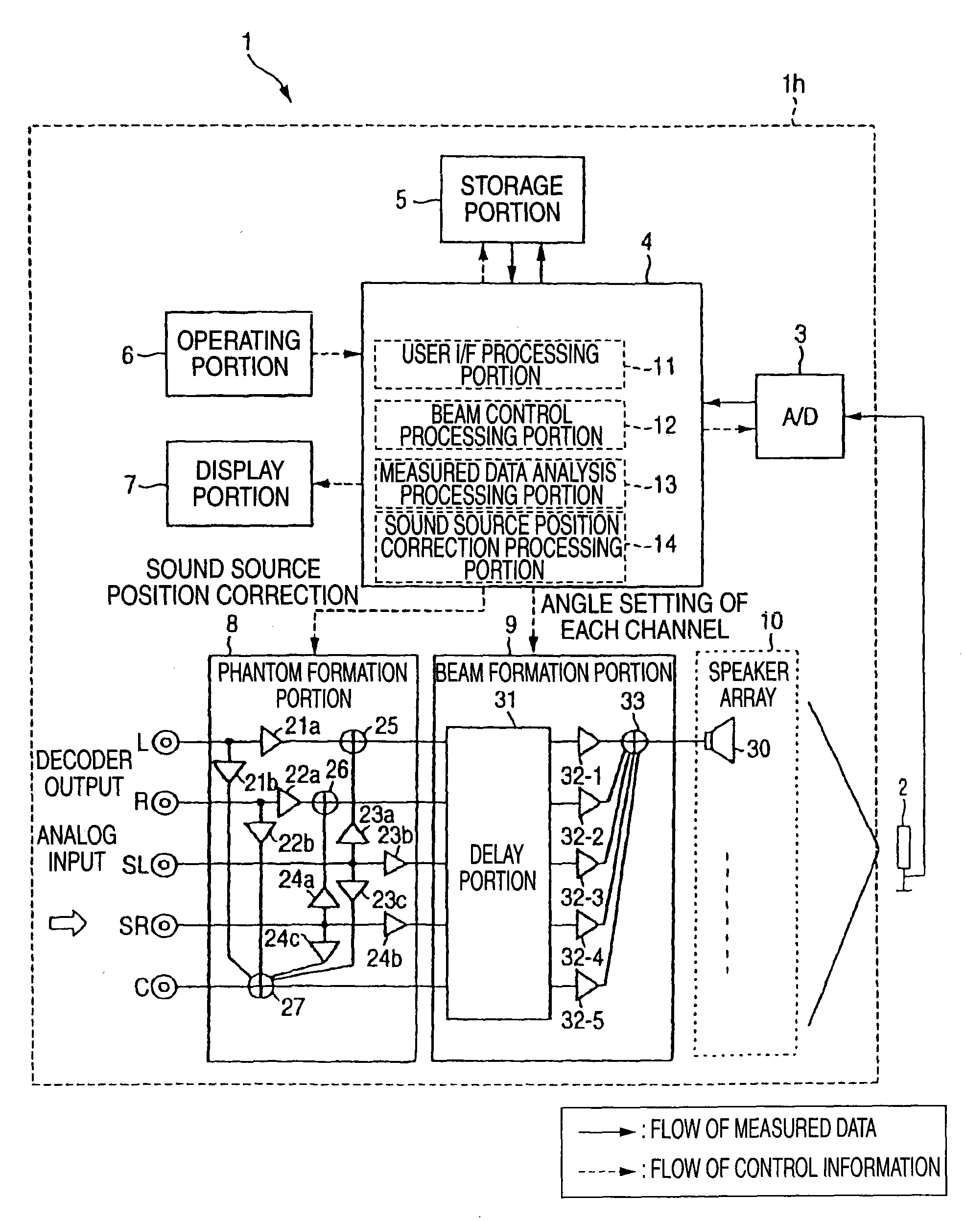
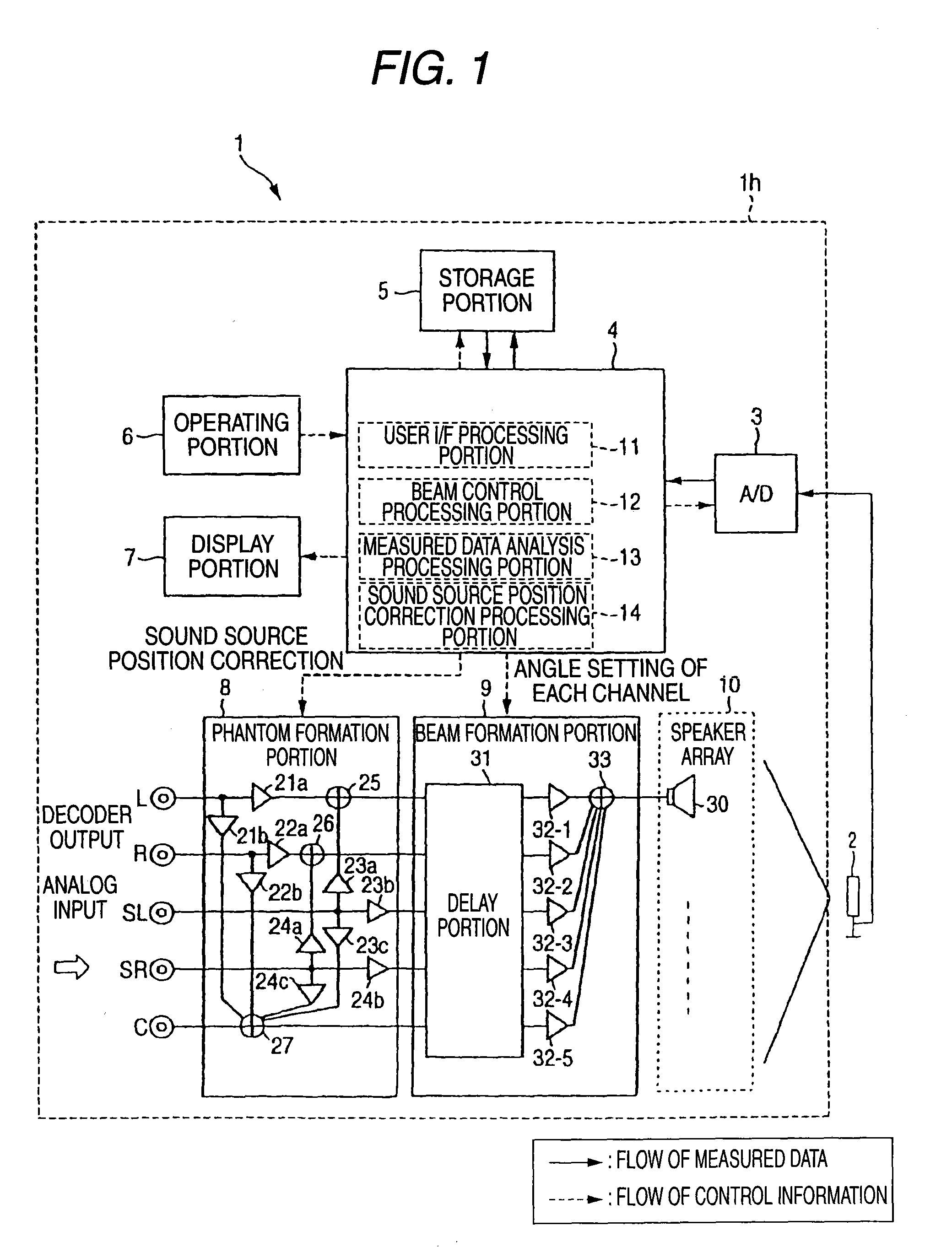
[0019]In order to reproduce a surround-sound in a background-art speaker array apparatus, it is necessary for a specialist to adjust directions to output audio beams of respective channels while reproducing sounds after this apparatus is installed. This causes increase in cost. In this configuration, when the speaker array apparatus is installed in a room, a
microphone is placed in a listening position of a user. Audio beams of a test sound are output from the speaker array while being turned (swept) automatically. In this event, the audio beams are collected with the
microphone. Peaks of the
signal level are detected based on test sounds output from the speaker array directly to the
microphone or test sounds reflected to the microphone from walls of the room. Accordingly, in order to reproduce an optimum surround-sound in the listening position, the positions of the walls of the room where the audio beams output from the array speaker should be reflected so that a multi-channel
audio signal can be reproduced optimally can be detected easily in a short time. In addition, sweep angles with which the peaks were detected are set as angles with which audio beams should be output in respective channels of the multi-channel
audio signal. Thus, the user can easily do settings for reproducing a multi-channel surround-sound after the installation of the speaker array apparatus regardless of the shape of the room where the speaker array apparatus is installed, the
layout of furniture, and so on.(2) The beam setting portion sets a sweep angle of a peak where the
signal level of the test sound is the highest, as a beam output angle of a center channel of the multi-channel surround-sound.
[0022]Assume that the beam output angle of the center channel of the multi-channel surround-sound is shifted from a direction perpendicular to the front surface of the speaker array by an angle not smaller than a predetermined angle. In this case, if the surround-sound is reproduced with the peaks set as the output angles of the audio beams respectively, the surround-sound will be off balance. In this configuration, at least the informing portion gives the
user information to prompt the user to change the listening position or to prompt the user to change the sound
reproduction method. Accordingly, in the aforementioned case, settings can be changed so that the surround-sound can be reproduced in a balanced manner.(5) When the output angles set for the channels respectively are asymmetric with respect to the beam output angle of the center channel, the beam setting portion forms a
signal localization of one of the channels as a phantom using audio beams directed in a plurality of directions so as to form a symmetric
sound field.
[0026]In this configuration, the
signal level is modulated with an envelope having a maximum almost at the center of a sweep range of the audio beams. When the listening position of the speaker array apparatus is set almost at the center of the sweep range of the audio beams, a peak to be set as the output angle of the center channel can be detected easily. When the output angle of the audio beam of the center channel is determined, left and right with respect to the user can be determined. Thus, based on this output angle, output angles of the other channels can be set easily.(8) The speaker array outputs audio beams based on a test audio signal having no correlation and limited to a band where beams can be formed.
[0036]When the speaker array apparatus according to the present invention is installed in a room, a microphone is placed in a listening position of a user, and a test sound is output from a speaker array so as to turn (sweep with) audio beams automatically. In this event, the audio beams are collected by the microphone. Thus, sounds output from the speaker array directly to the microphone or sounds reflected from walls of the room to the microphone can be detected as peaks of the
signal level. By this, in order to reproduce an optimum surround-sound in the listening position, the positions of the walls of the room where the audio beams output from the array speaker should be reflected so that a multi-channel audio signal can be reproduced optimally can be detected easily in a short time. When the sweep angles with which the peaks were detected are set as angles with which audio beams of respective channels in a multi-channel audio signal should be output, the user can easily perform setting to reproduce the multi-channel surround-sound after the installation of the speaker array apparatus regardless of the shape of the room where the speaker array apparatus is installed, the
layout of furniture, or the like.BRIEF DESCRIPTION OF THE DRAWINGS

