
Ablation device for cardiac tissue, in particular for a circular lesion around a vessel orifice in the heart

Active Publication Date: 2005-12-27
AFREEZE
View PDF10 Cites 62 Cited by
  • Summary
  • Abstract
  • Description
  • Claims
  • Application Information

AI Technical Summary

Benefits of technology

[0010]The invention has as its object to present an ablation device whereby a circular lesion around or at a vessel orifice in the heart can be formed in a manner that is reliable and with an application technique that is easy to perform.
[0012]The embodiment, according to the invention, of the catheter helps obtain reliable positioning by the ablation device being fixed in the vessel orifice. On the other hand, the ablation applicator, by its encircling in the way of a circular arc in the ablation position, is brought quasi shape-inherently into a correct position for applying the circular lesion, preferably when the applicator is disposed proximally in front of the abutment device around the vessel orifice. A high degree of application reliability is achieved, accompanied with corresponding improvement of the therapeutic success.
[0013]A preferred embodiment provides for a combination of two catheters, namely a steerable positioning catheter, the distal end of which is equipped with an abutment device, and an ablation catheter coupled there-with, the distal end of which holds the ablation applicator. This separation of functions renders the positioning catheter very compact and thus flexible and excellently steerable, which works especially in favour of possible positioning in vessel orifices.
[0017]A coverage of at least 180° by the ablation applicator ensures that a completely closed circular lesion can be attained with only one rotation of the ablation catheter.

Problems solved by technology

The known ablation devices are not practical for lesions of this shape, there being no or hardly any possibility of putting into practice an annular arrangement of the ablation electrodes around or at the pv orifice.

Method used


Image

  • Ablation device for cardiac tissue, in particular for a circular lesion around a vessel orifice in the heart
  • Ablation device for cardiac tissue, in particular for a circular lesion around a vessel orifice in the heart
  • Ablation device for cardiac tissue, in particular for a circular lesion around a vessel orifice in the heart

Examples


Embodiment Construction

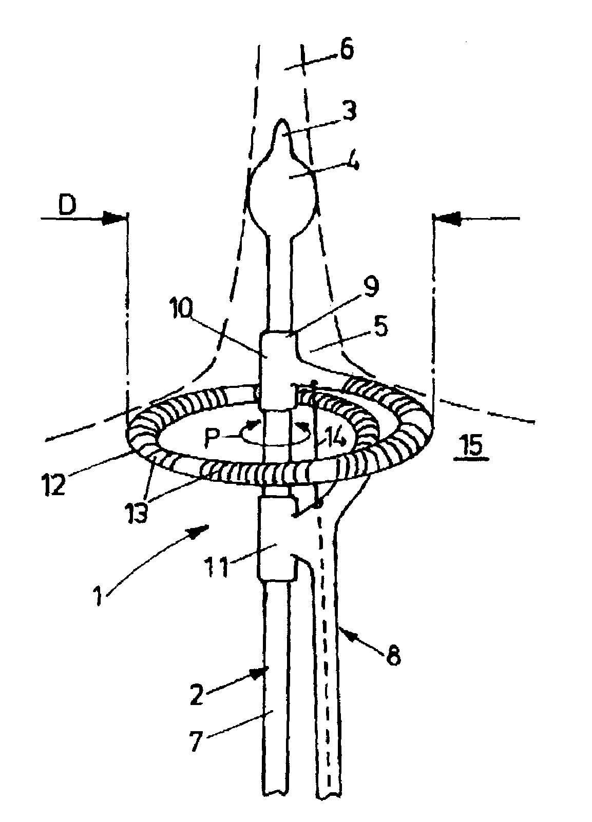
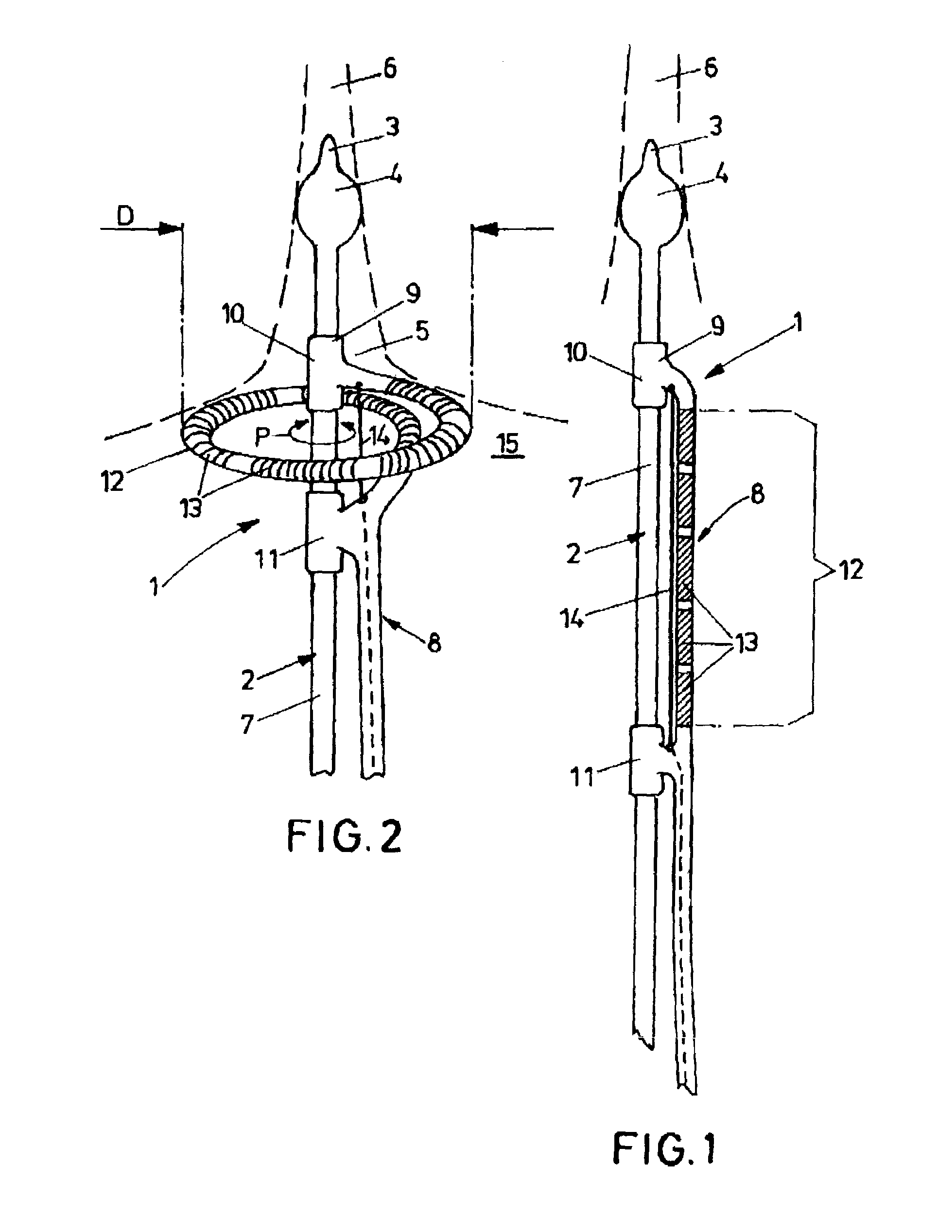
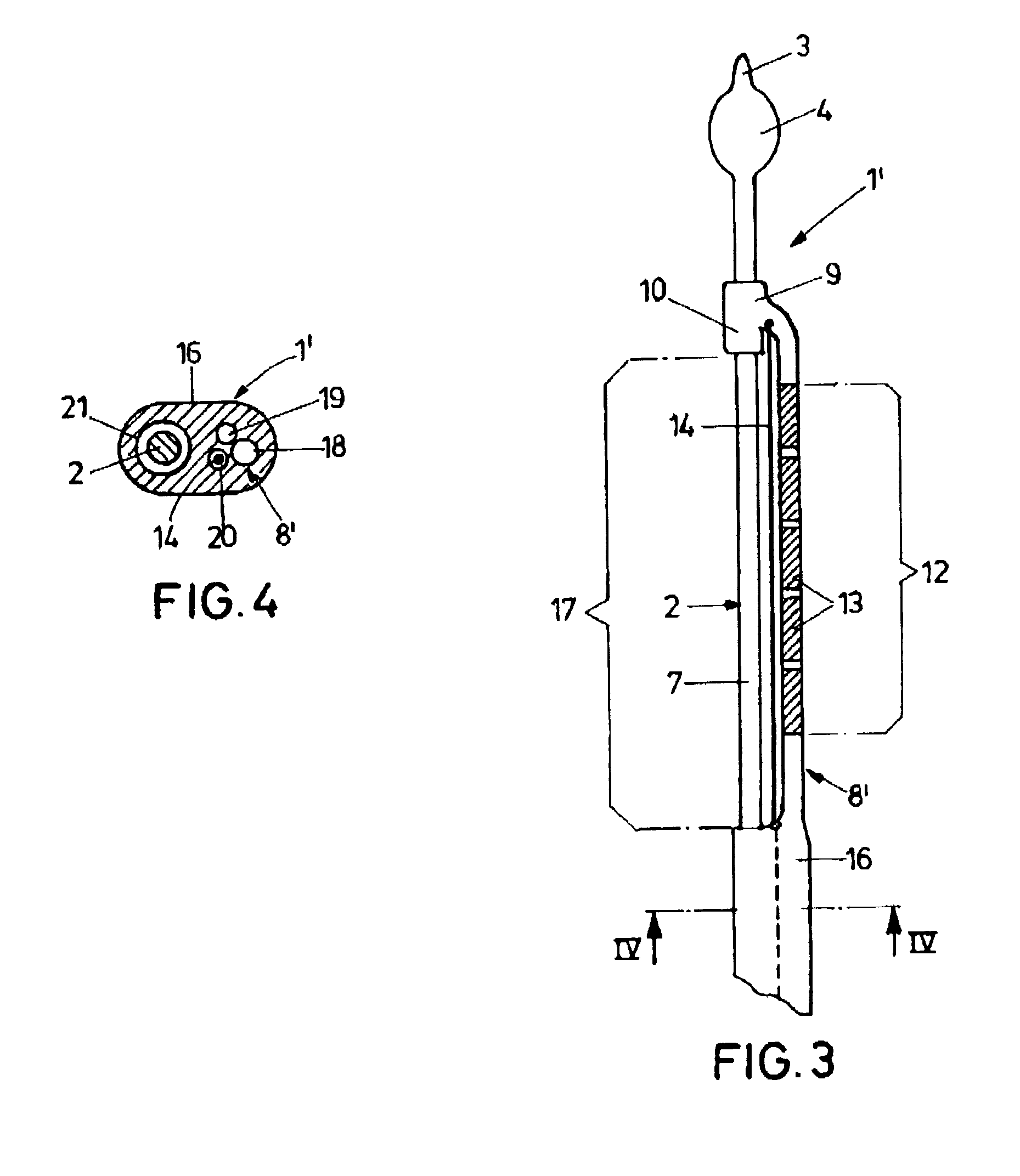
[0024]As becomes clear from FIG. 1, the ablation device, which has been marked in its entirety with the numeral l, incorporates a steerable positioning catheter 2, which has in front of its distal end 3 a dilatable balloon 4. In FIGS. 1 to 3, the balloon 4 is shown in its expanded condition in which it fixes the distal end 3 of the catheter 2 in an orifice opening 5 of a pulmonary vein 6 (shown in a dashed line in FIG. 2) into the atrium of the heart. The positioning catheter 2 may be designed conventionally and ma) be provided, for example with a lumen for a guide wire, a deflection device for the targeted guiding of the distal end 3, etc. Other supplemental devices have furthermore already been mentioned in the introductory part of the specification.

[0025]An ablation catheter 8 is disposed on the shank 7 of the positioning catheter 2. For displaceable guidance of the ablation catheter 8 on the positioning catheter 2, provision is made for two guide sleeves 10, 11, which are formed...


PUM


Abstract

An ablation device for cardiac tissue, in particular for forming a circular lesion around a vessel orifice in the heart, comprisesa catheter which, in the region of its distal end, is provided with an abutment device for holding the distal end on a cardiac vessel orifice, anda linear ablation applicator which is disposed proximally or distally relative to the abutment device of the catheter and is movable from a straight passive position into a radially expanded, approximately circular-arc-type encircling ablation position.

Description

BACKGROUND OF THE INVENTION[0001]1. Field of the Invention[0002]The invention relates to an ablation device for cardiac tissue, in particular for forming a circular lesion around a vessel orifice in the heart, comprising a catheter which, in the region of its distal end, is provided with an abutment device for holding the distal end on a cardiac vessel orifice.[0003]2. Background Art[0004]Regarding the background of the invention it can be stated that catheter ablation is a therapy that is used to an increasing degree to treat certain types of arrhythmia. In the process, a lesion—i.e., a denaturation of tissue along the line of a tissue scarring—is created with the aid of the ablation applicator of the catheter at a certain location in the myocardial tissue in order to sever the faulty electrical stimulus pathways at that location that are responsible for arrhythmia. The introduction of energy into the myocardial tissue via the ablation applicator, as a rule, takes place by means of...

Claims


Application Information

Patent Timeline
IPC IPC(8): A61B18/14
CPCA61B18/1492A61B2018/00196A61B2018/00267A61B2018/00285A61B2018/00577A61B2018/00839A61B2018/1435
Inventor HINTRINGER, FLORIANGEISTERT, WOLFGANG
Owner AFREEZE
Learn More