

Band saw blade
- Summary
- Abstract
- Description
- Claims
- Application Information
AI Technical Summary
Benefits of technology
Problems solved by technology
Method used
Image

Examples
Example
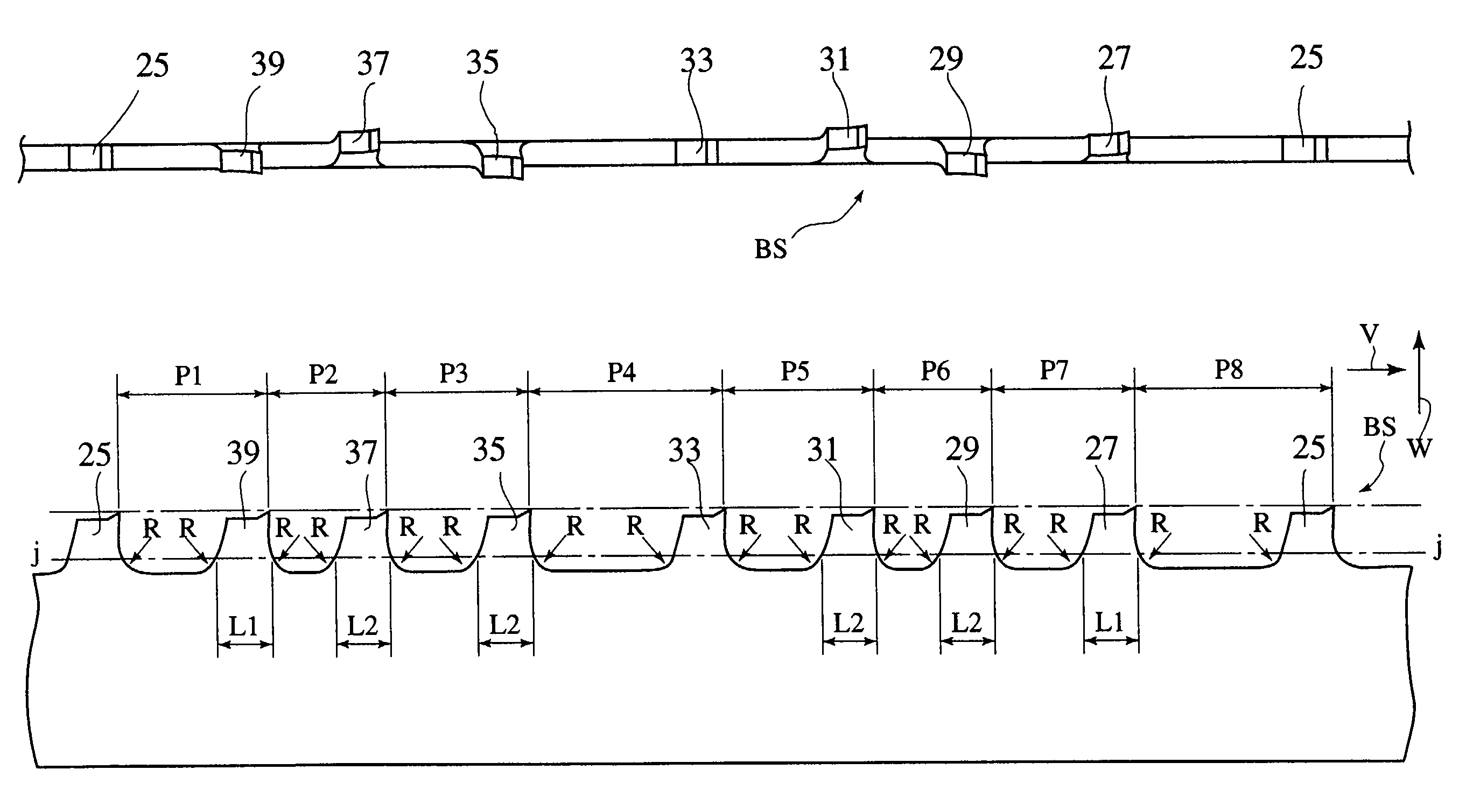
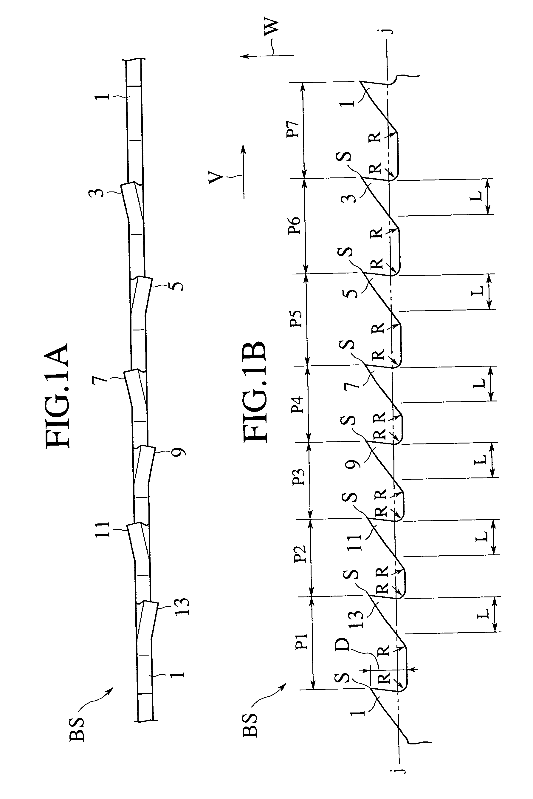
[0048]A second embodiment is shown in FIGS. 2A and 2B, and a band saw blade BS with a variable pitch comprising seven teeth disposed at seven kinds of different pitches P1 to P7 as one group is shown. Among the seven teeth 1, 3, 5, 7, 9, 11 and 13, the tooth 1 is an unset tooth, the teeth 3, 7 and 11 are left-set teeth and the teeth 5, 9 and 13 are right-set teeth. Further, all of positive rake angles and radial relief backs of the respective teeth 1 to 13 are constant, and bending lengths L of each of the teeth 3 to 13 on the setting and bending position j—j line are all set to be constant. Further, the teeth bottoms R1 to R7 respectively have a different curvature, and it is set that a contact point of the tooth bottom R is not closer to the tip S than a crossing point X1 between the front surface T and the j—j line and a crossing point X2 between the surface of relief and the j—j line. Accordingly, all of the tip end shapes from the j—j line to the tip S are constant. In this cas...
Example
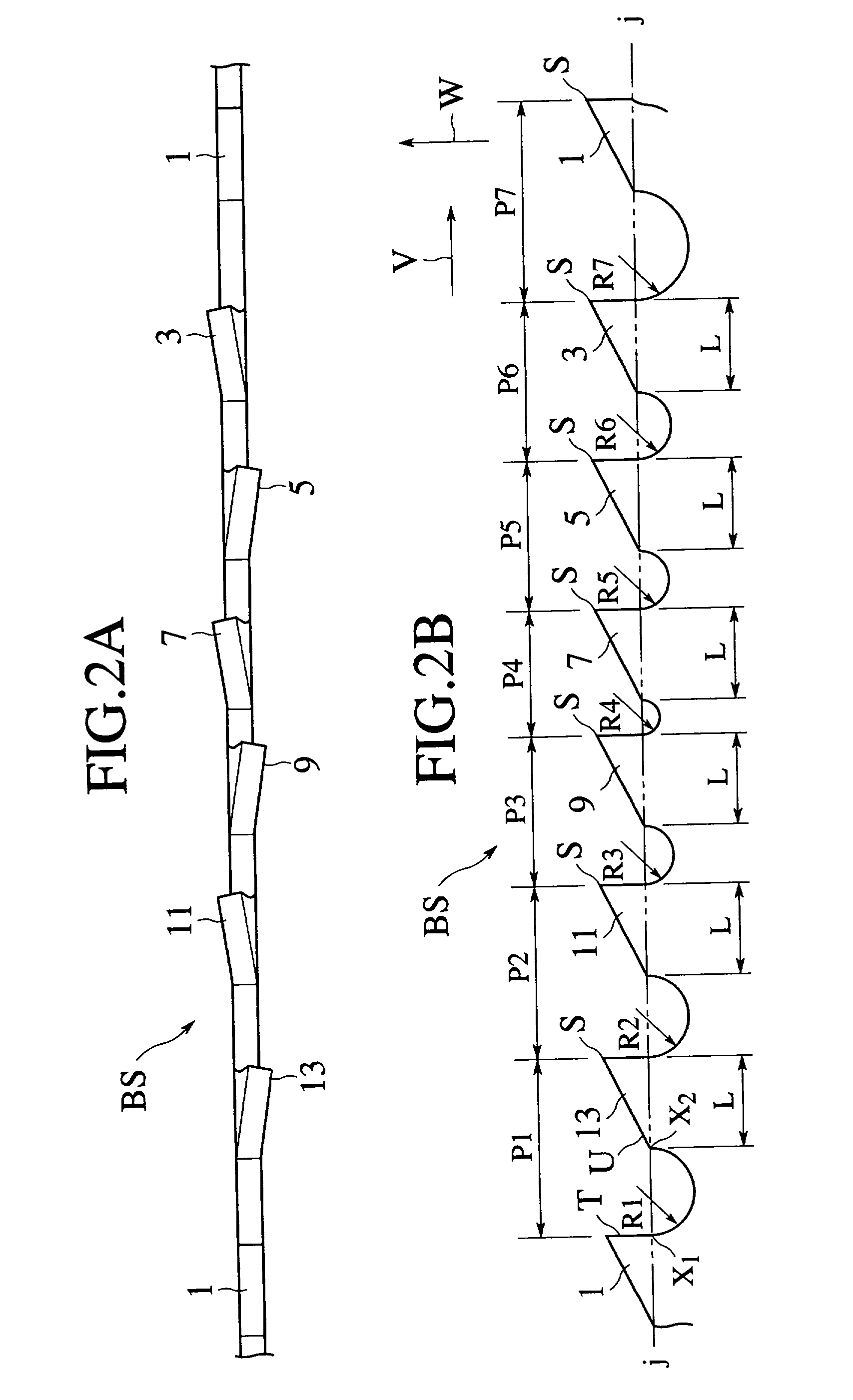
[0051]A third embodiment is shown in FIGS. 3A and 3B, and a band saw blade BS with a variable pitch comprising seven teeth disposed at seven kinds of different pitches P1 to P7 as one group is shown. Among the seven teeth 1, 3, 5, 7, 9, 11 and 13, the tooth 1 is an unset tooth, the teeth 3, 7 and 11 are left-set teeth and the teeth 5, 9 and 13 are right-set teeth. The tip end shapes of the set teeth 3 and 5 are formed to be equal to each other, and the tip end shapes of the set teeth 7, 9, 11 and 13 are formed to be equal to each other. Then, the radial relief backs α6 and α5 of the tip front end portion in the right and left set teeth 3 and 5 following to the unset tooth 1 are set to be smaller than the radial relief backs α4, α3, α2 and α1 of the other set teeth 7, 9, 11 and 13. Further, since the setting and bending position j—j line is not in contact with the tooth bottom R portion of any of the set teeth 3 to 13, the point X1 is disposed at a position of the line having the sam...
Example
[0054]A fourth embodiment is shown in FIGS. 4A and 4B, and a band saw blade BS with a variable pitch comprising seven teeth disposed at seven kinds of different pitches P1 to P7 as one group is shown. Among the seven teeth 1, 3, 5, 7, 9, 11 and 13, the tooth 1 is an unset tooth, the teeth 3, 7 and 11 are left-set teeth and the teeth 5, 9 and 13 are right-set teeth. The tip end shapes of the set teeth 3 and 5 are formed to be equal to each other, and the tip end shapes of the set teeth 7, 9, 11 and 13 are formed to be equal to each other. The positive rake angles θ6 and θ5 of the right and left set teeth 3 and 5 following to the unset tooth 1 are set to be smaller than the positive rake angles θ4, θ3, θ2 and θ1 of the other set teeth 7, 9, 11 and 13.
[0055]Further, since the setting and bending position j—j line is not in contact with the tooth bottom R portion of any of the set teeth 3 to 13, the point X1 is disposed at a position of the line having the same bending length L as that ...
PUM
| Property | Measurement | Unit |
|---|---|---|
| Radius | aaaaa | aaaaa |
Abstract
Description
Claims
Application Information