Tray type card connector

a card connector and tray-type technology, applied in the direction of conveying record carriers, coupling device connections, instruments, etc., can solve the problems of card connectors not being compatible with waterproof devices, card tray cannot be easily ejected, etc., and achieve the effect of reducing the number of components and being easy to pull ou

Active Publication Date: 2015-06-04
SMK CORP
View PDF0 Cites 57 Cited by
  • Summary
  • Abstract
  • Description
  • Claims
  • Application Information

AI Technical Summary

Benefits of technology

[0020]Furthermore, in the present invention, the water-sealing pin has a slip-out preventing portion that juts out outwardly to get engaged with a rear end opening edge portion of the pin insertion hole, and the water-sealing pin is held in the pin insertion hole so as to be movable and to be incapable of slipping out. Accordingly, the water-sealing pin can be suitably retained in the front cover portion.
[0021]Moreover, in the present invention, the water-sealing pin is integrally formed with the operation member. Accordingly, the number of components can be reduced.
[0022]In addition, in the present invention, the card tray has the front cover portion at a front end portion of a tray main body where the card is held, such that the front cover portion is movable relative to the tray main body, and has transmission means for transmitting a force in a tray pull-out direction to the tray main body, the force acting on the front cover portion being moved to a desired pull-out position relative to the tray main body. The front cover portion is allowed to move relative to the tray main body to pull out the card tray using the front cover portion as a finger holding part. Accordingly, in a state in which the card tray is inserted into an electronic device, the casing opening portion can be suitably made watertight by the front cover portion and the cover water-sealing member. When the card tray is pulled out, only resistance by the cover water-sealing member acts on the front cover portion. Thus, the front cover portion can be pulled out relative to the tray main body with a small force. After pulling out, a force of a certain magnitude or more can be allowed to act on the entire card tray using the front cover portion as a finger holding part. Accordingly, the card tray can be easily pulled out of the housing and the electronic device.
[0023]In addition, in the present invention, the tray type card connector further includes: an ejector that moves with the card tray; a push-out spring that biases the ejector in a push-out direction; a heart cam disposed in one of the housing and the ejector; a loop-shaped pin guide groove provided around the heart cam; and a lock pin that has, at its one end, an engagement pin portion slidably inserted into the pin guide groove, and that is turnably supported, at its other end, by an other one of the housing and the ejector. By initial card tray push operation, the engagement pin portion moves to a position where the engagement pin portion is engaged with the heart cam, by which movement in a tray push-out direction of the ejector is restricted. By another card tray push operation, the engagement pin portion is disengaged from the heart cam, by which the engagement is released. Accordingly, in a state in which the card tray is inserted into an electronic device, the casing opening portion can be suitably made watertight by the front cover portion and the cover water-sealing member. When the card tray is pulled out, only by push operation of the card tray, the card tray can be easily pulled out.

Problems solved by technology

In such a tray type card connector, when the front cover portion of the card tray fits in the casing opening portion, the card tray cannot be easily ejected.
Since the pin insertion hole passes through internally and externally of the casing of the electronic device, there is a problem that the card connector is not compatible with waterproof devices.

Method used


Image

  • Tray type card connector
  • Tray type card connector
  • Tray type card connector

Examples


first embodiment

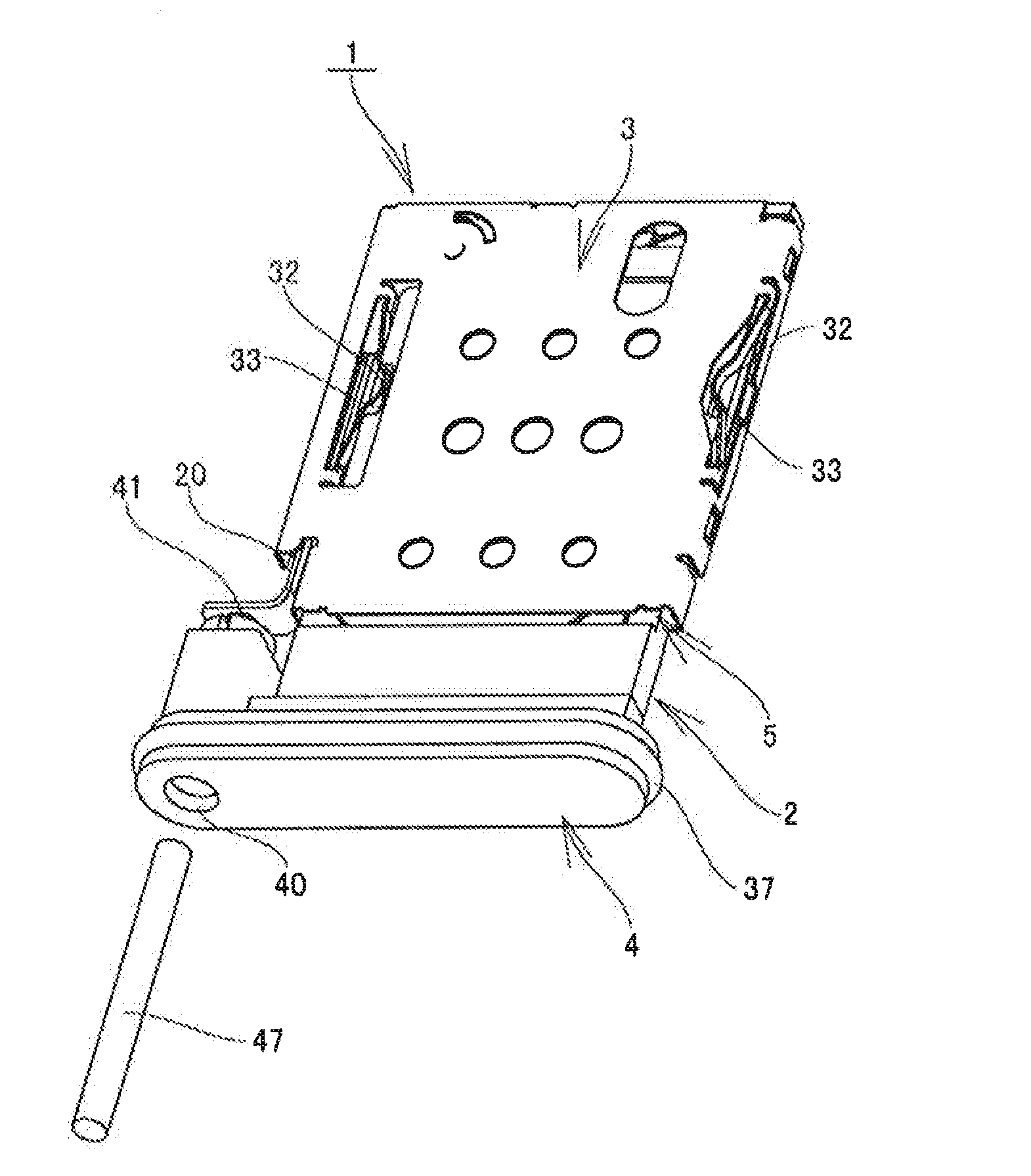
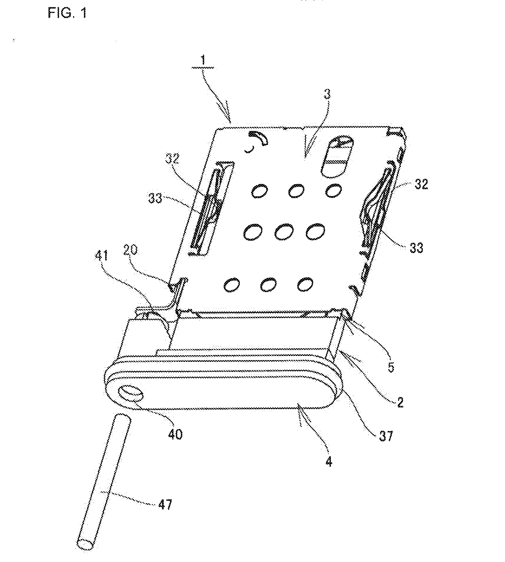
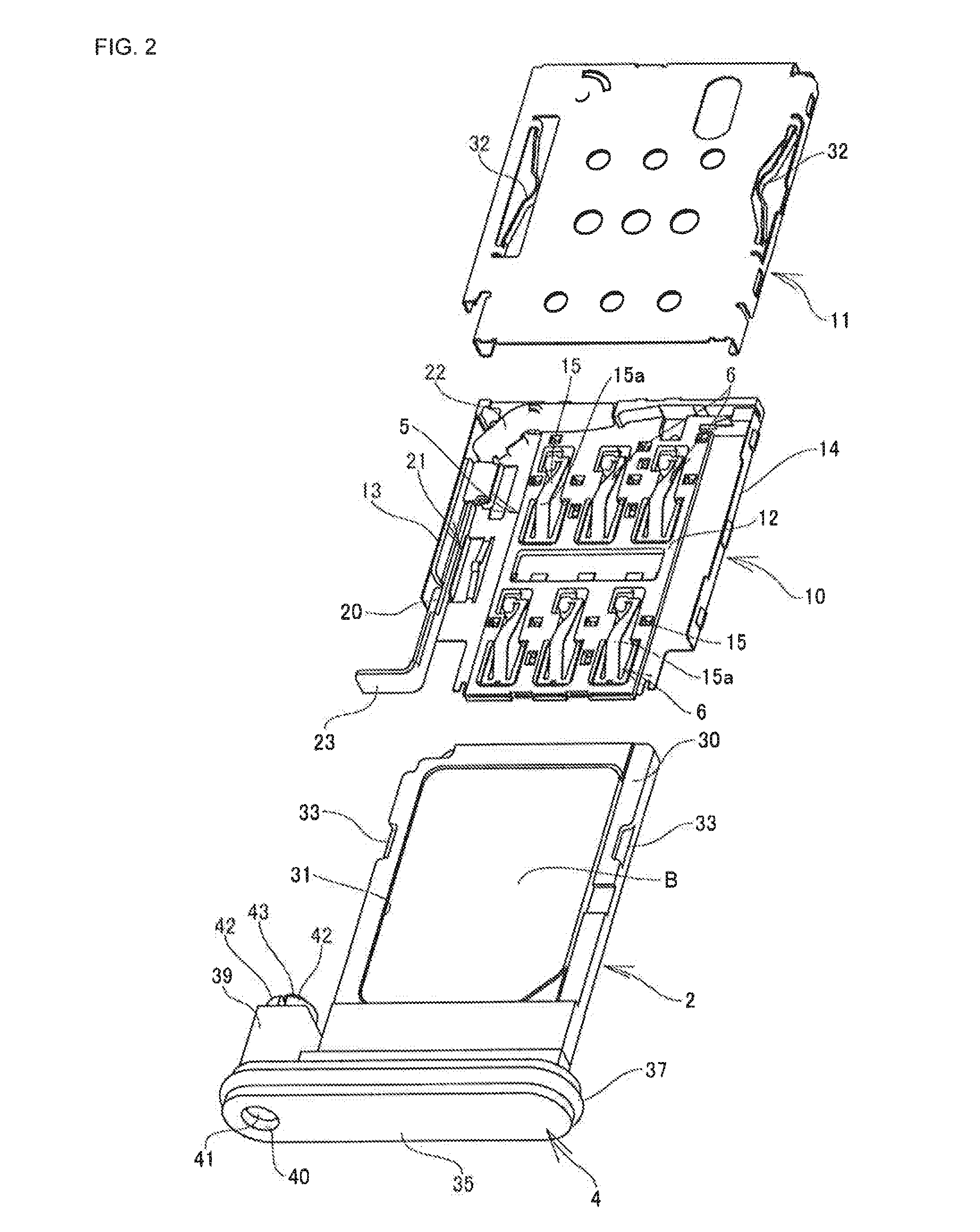
[0037]Next, a tray type card connector 1 according to the present invention will be described based on an implementation example shown in FIGS. 1 to 6.

[0038]Note that in the drawings reference sign A indicates an electronic device such as a mobile phone or a smartphone, and reference sign B indicates a card such as an IC card. Note also that in the present implementation example a description is made with the front side in a card tray insertion and removal direction being “front” and the back side being “rear”.

[0039]The electronic device A is structured such that the tray type card connector 1 is used for connection of the card B such as an IC card, and by inserting and removing a card tray 2 into / from the electronic device A through a casing opening portion Aa opened at a lateral surface portion of a casing of the electronic device A, the card B can be mounted and demounted on / from a housing 3 disposed in the electronic device A, and the casing opening portion Aa can be closed by a...

second embodiment

[0071]Next, a tray type card connector according to the present invention will be described based on an implementation example shown in FIGS. 7 to 10A and 10B. Note that a description is made denoting the same components as those of the above-described implementation example by the same reference signs, and reference sign A indicates an electronic device and reference sign B indicates a card.

[0072]This tray type card connector 50 includes a card tray 51 where the card B is held; a housing 53 having a tray insertion portion 52 into which the card tray 51 is inserted; and a plurality of contacts 54, 54 . . . arranged in the housing 53 so as to project within the tray insertion portion 52. By inserting the card tray 51 into the housing 53 through a casing opening portion Aa, pad portions b1, b1 . . . of the card B held in the card tray 51 come into contact with the corresponding contacts 54, 54 . . . , by which the card B is electrically connected to a substrate having the card connect...


PUM


Abstract

Provided is a tray type card connector that is compatible with waterproof electronic devices and that can easily perform the insertion and removal of a card into/from the electronic devices. A tray type card connector includes a card tray; a housing having a tray insertion portion; a plurality of contacts arranged in the housing so as to project within the tray insertion portion; a front cover portion fitting in a casing opening portion opened at a lateral surface portion of a casing of an electronic device A, at a front end portion of the card tray; a ring-shaped cover water-sealing member made of an elastic material at an outer periphery portion of the front cover portion.

Description

CROSS-REFERENCE TO RELATED APPLICATION[0001]This application claims priority of Japanese Patent Application No. 2013-249878 filed Dec. 3, 2013, which is incorporated herein by reference in its entirety.BACKGROUND[0002]1. Technical Field[0003]The present invention relates to a card connector for connecting a card such as an IC card or a flash memory card into a mobile phone, a smartphone, or other electronic devices. More particularly, the present invention relates to a tray type card connector compatible with waterproof electronic devices.[0004]2. Related Art[0005]Conventionally, for an external storage medium for an electronic device such as a mobile phone or a smartphone, a card such as an IC card or a flash memory card is used. The card and a printed wiring board installed in the electronic device are electrically connected to each other through a card connector.[0006]There is known a card connector that includes a housing disposed in an electronic device; a card tray that is ins...

Claims


Application Information

Patent Timeline
Patent Type & Authority Applications(United States)
IPC IPC(8): H01R13/52H01R12/71
CPCH01R12/714H01R13/5213G06K7/0021G06K13/0831H01R13/5219H01R2201/06
Inventor EJIRI, KOICHIRO
Owner SMK CORP
Why Eureka
Try Eureka