Electric motor, rotary actuator and rotary apparatus

a technology of rotary actuators and motors, applied in the direction of supporting/enclosed/casings, mechanical energy handling, dynamo-electric machines, etc., can solve the problems of large number of components, tendency for vibration, performance and efficiency degradation of electric motors, etc., to improve the manufacturing efficiency of rotary actuators, simplify the task of positioning the plurality of sensors inside the housing, and simplify assembly tasks. effect of rotary actuators

Inactive Publication Date: 2008-09-18
KEIHIN CORP
View PDF3 Cites 70 Cited by
  • Summary
  • Abstract
  • Description
  • Claims
  • Application Information

AI Technical Summary

Benefits of technology

[0045]According to the above described rotary actuator, by placing both the motor pole detection sensors and the output shaft angle detection sensor on the output shaft side relative to the rotor, this plurality of sensors can be integrally fixed to the same bracket portion that forms the housing. By integrally fixing this plurality of sensors to the same bracket portion, the task of positioning the plurality of sensors inside the housing is simplified. Moreover, because it is no longer necessary to assemble the sensors individually inside the housing, the assembly tasks required to manufacture the rotary actuator can be simplified.
[0046]Furthermore, in the case of this structure, because the respective electrical connections between t

Problems solved by technology

In this manner, in a conventional rotary actuator, the problem arises that there are a large number of components.
Because the rotor shaft of the electric motor is supported inside the second shaft, the coaxial accuracy of this rotor shaft often deteriorates resulting in there being a tendency for vibration to occur.
Consequently, there is a tendency for the performance and efficiency of the electric motor to deteriorate.
However, when, as in the above described conventional electric motor, the task of assembling a large number of electrical components still remains after the above described electrical connectio

Method used


Image

  • Electric motor, rotary actuator and rotary apparatus
  • Electric motor, rotary actuator and rotary apparatus
  • Electric motor, rotary actuator and rotary apparatus

Examples


first embodiment

[0070]the present invention will be described below with reference to the drawings.

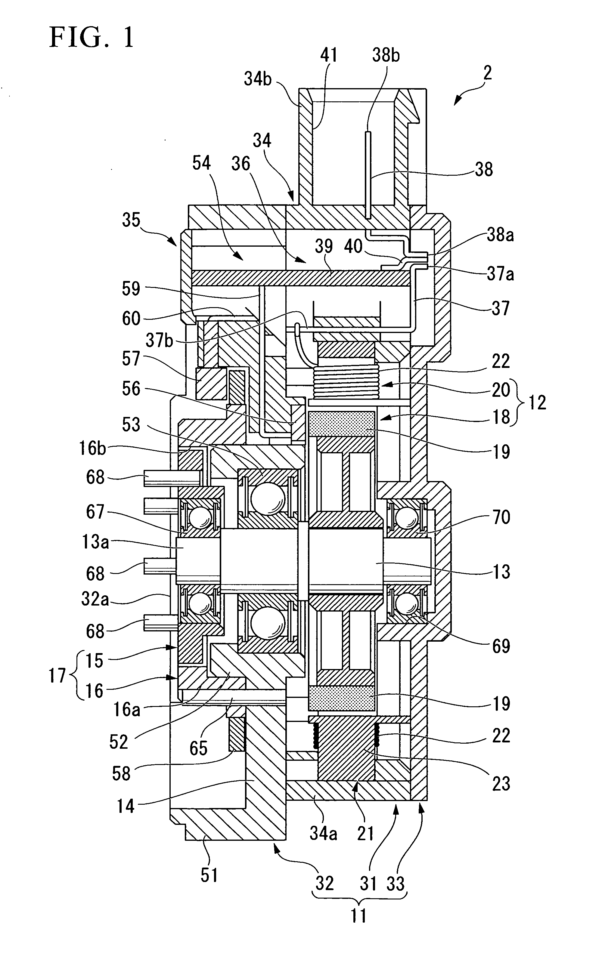
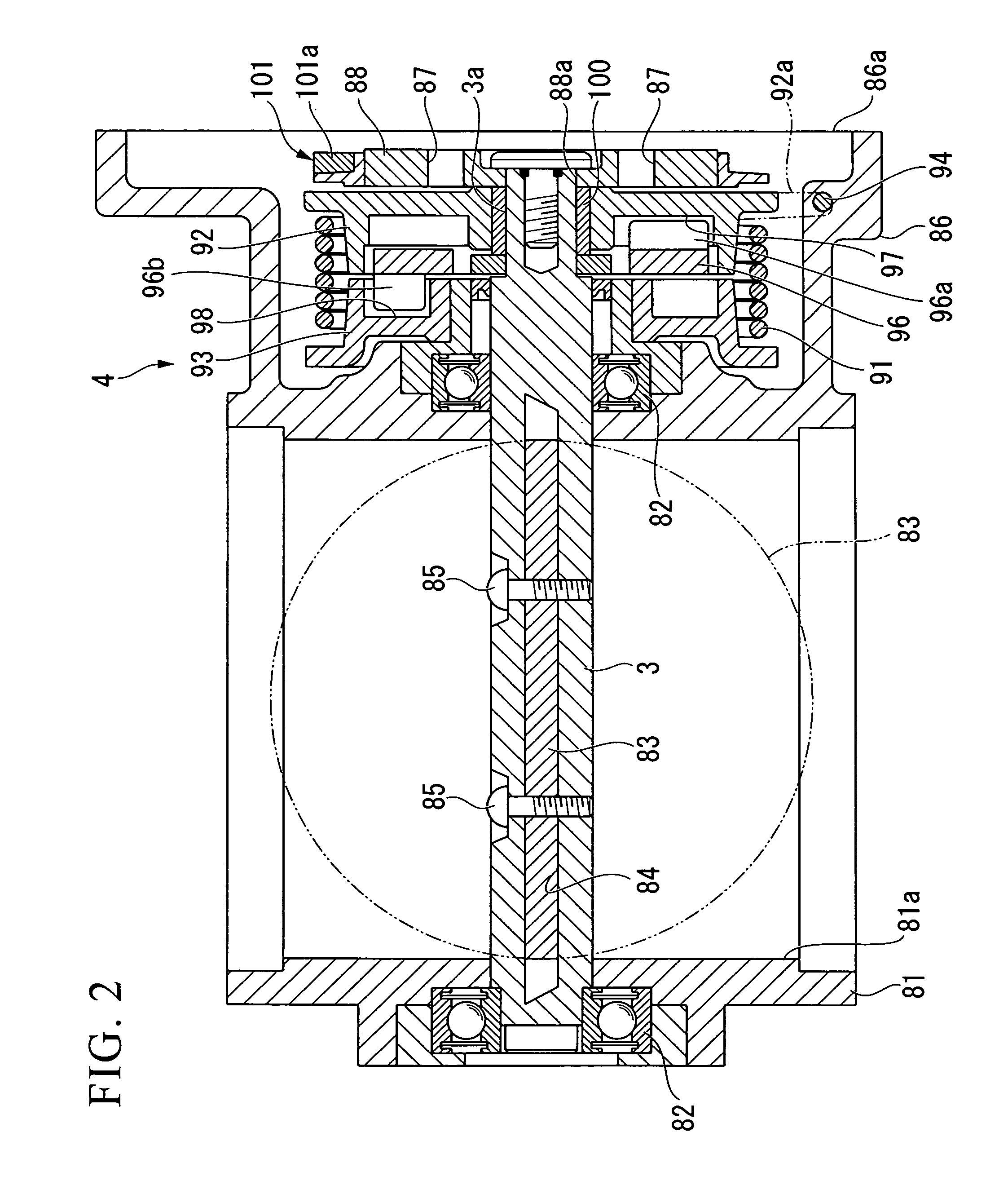
[0071]FIG. 1 through FIG. 10 show a first embodiment of the present invention. As is shown in the overall views in FIG. 9 and FIG. 10, a rotary apparatus 1 of the present embodiment is a throttle valve apparatus that is used to adjust an engine intake amount. This rotary apparatus 1 includes a rotary actuator 2 and an output mechanism 4 which has an output shaft 3 (see FIG. 2 and the like) that forms the valve shaft of the throttle valve.

(Rotary Actuator)

[0072]In this rotary actuator 2, as is shown in FIG. 1 and FIG. 3, an electric motor 12 is housed inside a housing 11. One end portion of a rotor shaft 13 of this electric motor 12 penetrates a wall (i.e., a flat plate portion 14 which is described below) of the housing 11, and protrudes from an outer surface of the housing 11. A reduction gear 17 that includes an external gear 15 and an internal gear 16 is provided on a protruding end portion 13a of ...

second embodiment

[0114]the present invention will now be described below with reference to the drawings.

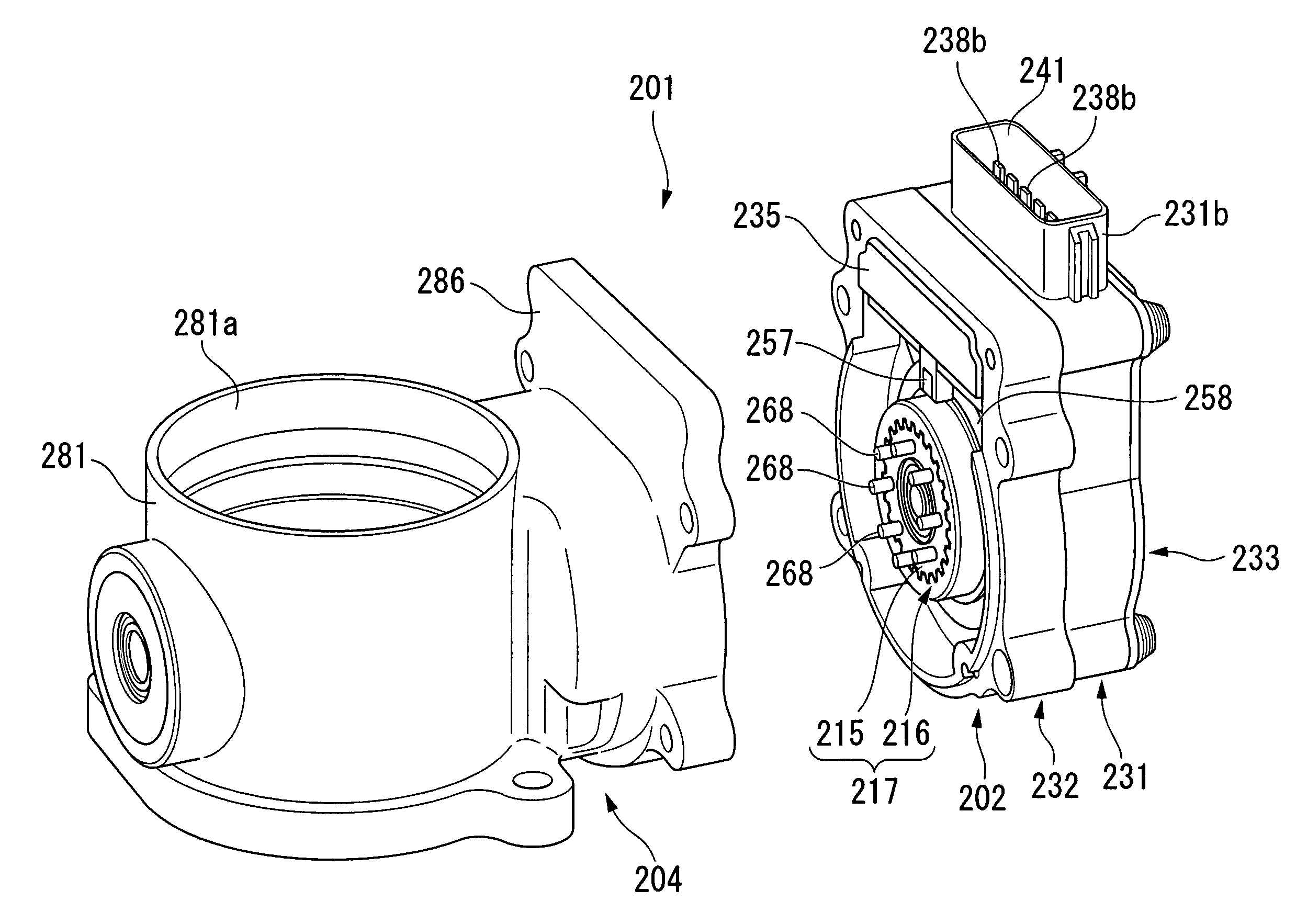
[0115]FIG. 13 through FIG. 22 show the second embodiment of the present invention. As is shown in FIG. 21 and FIG. 22, a rotary actuator 202 of the present embodiment includes an output mechanism 204 which has an output shaft 203 (see FIG. 14 and the like) that forms the valve shaft of the throttle valve and a throttle valve device (rotary apparatus) 201 that is used to adjust an engine intake amount.

(Rotary Actuator)

[0116]In this rotary actuator 202, as is shown in FIG. 13 and FIG. 15, an electric motor 212 is housed inside a housing 211. One end portion of a rotor shaft 213 (i.e., a shaft portion of a rotor 218 which is described below) of this electric motor 212 penetrates a wall (i.e., a flat plate portion 214 which is described below) of the housing 211, and protrudes from an outer surface of the housing 211. A reduction gear 217 that includes an external gear 215 and an internal gear 216 is ...


PUM


Abstract

A rotary actuator including: a housing that rotatably supports thereinside a rotor shaft of an electric motor; an eccentric shaft portion that is provided on a protruding end portion of the rotor shaft that protrudes outside the housing; an external gear that is rotatably supported on the eccentric shaft portion via a bearing; an internal gear that is fixed to an outer surface of the housing and meshes with the external gear; and a transmitting portion that is provided on the external gear, and transmits rotation force to an external output shaft.

Description

[0001]Priority is claimed on: Japanese Patent Application No. 2007-068768, filed on Mar. 16, 2007; Japanese Patent Application No. 2007-069358, filed on Mar. 16, 2007; and Japanese Patent Application No. 2007-069359, filed on Mar. 16, 2007, the contents of which are incorporated herein by reference.BACKGROUND OF THE INVENTION[0002]1. Field of the Invention[0003]The present invention relates to an electric motor, a rotary actuator that is provided with this electric motor, and a rotary apparatus that uses this rotary actuator.[0004]2. Description of Related Art[0005]The conventional technology of a rotary actuator and an electric motor provided for a rotary actuator is illustrated in Japanese Unexamined Patent Application, First Publication No. 2004-52928.[0006]This rotary actuator is constructed by placing a synchronous electric motor and an internally-meshing planetary reduction gear which is connected to a rotor shaft (i.e., a first shaft) of this synchronous electric motor inside...

Claims


Application Information

Patent Timeline
IPC IPC(8): H02K11/00H02K7/075H02K7/116
CPCH02K5/15H02K5/1732H02K5/225H02K11/0073H02K7/116H02K7/14H02K7/003H02K11/33
Inventor ABE, HIDEFUMISASAKI, HIDEKIMAYUMI, TOSHIROMATSUMOTO, EISHIN
Owner KEIHIN CORP
Why Eureka
Try Eureka