Dual-band multilayer bandpass filter

a bandpass filter and multi-layer technology, applied in multi-band filters, waveguides, electrical devices, etc., can solve the problems of limiting the size reduction that can be achieved, the dual-band bandpass filter cannot be produced, and the filter size is thus increased. achieve the effect of high performan

Inactive Publication Date: 2000-11-14
PANASONIC CORP
View PDF10 Cites 76 Cited by
  • Summary
  • Abstract
  • Description
  • Claims
  • Application Information

AI Technical Summary

Benefits of technology

Therefore, the object of the present invention is to provide a compact, high performance, dual-band multilayer bandpass filter.
The number of components required to achieve a dual-band bandpass filter can thus be reduced, and a compact dual-band multilayer bandpass filter with stable, high performance can be achieved within the footprint of a single multilayer filter by providing a phase shift circuit.

Problems solved by technology

A dual-band bandpass filter therefore cannot be produced by simply connecting two such coaxial filters together because the filters short at the passband of the other.
Filter size is thus increased, and there is a limit to the size reductions that can be achieved.

Method used


Image

  • Dual-band multilayer bandpass filter
  • Dual-band multilayer bandpass filter
  • Dual-band multilayer bandpass filter

Examples


first embodiment

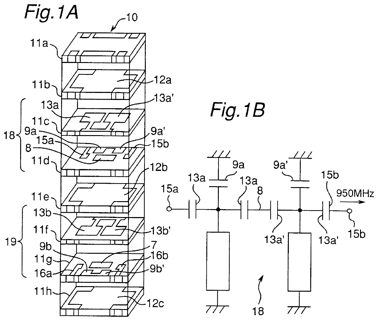
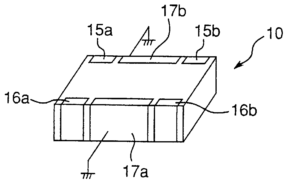
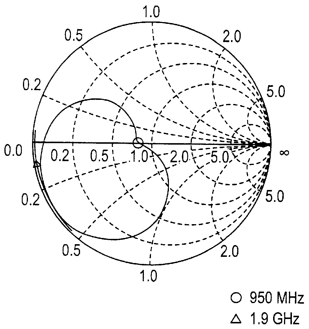
FIG. 1A is an exploded perspective view of a multilayer bandpass filter according to the present invention. FIG. 1B is an equivalent circuit of the multilayer bandpass filter of FIG. 1A. FIG. 2 is a perspective view showing the outside of the multilayer bandpass filter after the layers are stacked together. FIGS. 3 and 4 are Smith charts used to describe the phase characteristics of the first and second filters, respectively.

As shown in FIG. 1A, the multilayer filter 10 comprises a first filter unit 18 formed in ceramic layers 11c and 11d, and second filter unit 19 formed in ceramic layers 11f and 11g.

The layer 11c has a quarter-wave strip line resonator formed by electrodes 13a and 13a'. Electrodes 13a and 13a' are connected through a base electrode which is extended onto a front side surface of the layer 11c.

The layer 11d has: an input electrode 15a; capacitance electrodes 9a and 9a' connected through a base electrode which is extended onto a back side surface (not shown) of the l...

embodiment 2

Referring to FIG. 11, a second embodiment of the dual-band multilayer bandpass filter is shown. When compared with the first embodiment, such as shown in FIG. 1A, the difference is that ceramic layers 11i and 11j are further provided to form thereon the secondary filters. Furthermore, the quarter-wave strip line resonator formed by electrodes 13b and 13b' is oriented in opposite direction, i.e., in the same direction as the electrodes 13a and 13a'.

FIG. 12 shows an equivalent circuit diagram of the dual-band multilayer bandpass filter shown in FIG. 11.

As shown in FIG. 11, the multilayer filter 10 comprises: ceramic sheets 11a to 11h; shield electrodes 12a, 12b, and 12c; quarter-wave strip line resonator electrodes 13a, 13a', 13b and 13b' with each resonator grounded at the same side; capacitance electrodes 9a, 9a', 9b and 9b'; input / output terminals 15a and 15b for the first multilayer filter unit; input / output terminals 16a and 16b for the second multilayer filter unit; transmission...

second embodiment

It should be noted that the second embodiment has been described as a one-input, one-output type dual-band multilayer bandpass filter, but other types, such as a one-input, two-output type can be alternatively achieved by disposing a phase shift circuit as described above on the input side only, and providing a first filter output terminal and a second filter output terminal on the output side.

A two-input, one-output type can also be achieved by disposing a phase shift circuit as described above on the output side only with two terminals, one terminal for the first filter and one terminal for the second filter, provided on the input side.

It will also be obvious that while the resonators used in the dual-band multilayer bandpass filters described above are quarter-wave resonators grounded on one side, half-wave resonators and other types of resonators can be alternatively used. In addition, the dual-band multilayer bandpass filter of the invention has been described using only two re...


PUM


Abstract

PCT No. PCT / JP97 / 02660 Sec. 371 Date Jan. 20, 1999 Sec. 102(e) Date Jan. 20, 1999 PCT Filed Jul. 31, 1997 PCT Pub. No. WO98 / 05120 PCT Pub. Date Feb. 5, 1998A dual-band multilayer bandpass filter having a first filter unit (18) for filtering a first signal having a first frequency and a second filter unit (19) for filtering a second signal having a second frequency. First and second filter units are arranged in stacked ceramic layers. A first blocking element (20a, 20b; 25a, 25b; 25a', 25b'; 46a, 46b) is coupled to the first filter unit (18) for blocking the second signal from being applied to the first filter unit (18). A second blocking element (21a, 21b; 26a, 26b; 25c, 25d; 27a, 27b) is coupled to the second filter unit (19) for blocking the first signal from being applied to the second filter unit (19).

Description

The present invention relates to a dual-band multilayer bandpass filter used primarily in high frequency circuits.Dielectric filters are widely used in cellular telephones and other RF devices, and this use has driven demand for further reductions in size and weight accompanied by performance improvements. Dielectric filters can be broadly classified as devices using coaxial resonators and devices using multilayer resonators. Reducing the size of coaxial resonator devices, however, is generally considered to have nearly reached the practical limit, and multilayer filters are therefore preferable for further reducing the size and weight of RF devices.EP 0 641 035 A2 discloses a laminated dielectric filter comprising a strip line resonator electrode layer forming plural strip line resonators, and a capacity electrode layer, wherein the strip line resonator electrode layer and capacity electrode layer are sandwiched by two shield electrode layers, and the space between the two shield e...

Claims


Application Information

Patent Timeline
Patent Type & Authority Patents(United States)
IPC IPC(8): H01P1/213H01P1/203H01P1/20H03H7/01H01P1/205
CPCH03H7/0123H03H7/175H01P1/2135H01P1/20345H03H7/463H03H2250/00H03H2001/0085
Inventor KITAZAWA, SHOICHIYAMADA, TORUISHIZAKI, TOSHIOOGAWA, KOICHIFUJIKAWA, MAKOTOFUJISAWA, TADANORIISHIDA, KAORUNAGATOMI, YOSHITAKA
Owner PANASONIC CORP
Why Eureka
Try Eureka