Electromagnetic lens driving device

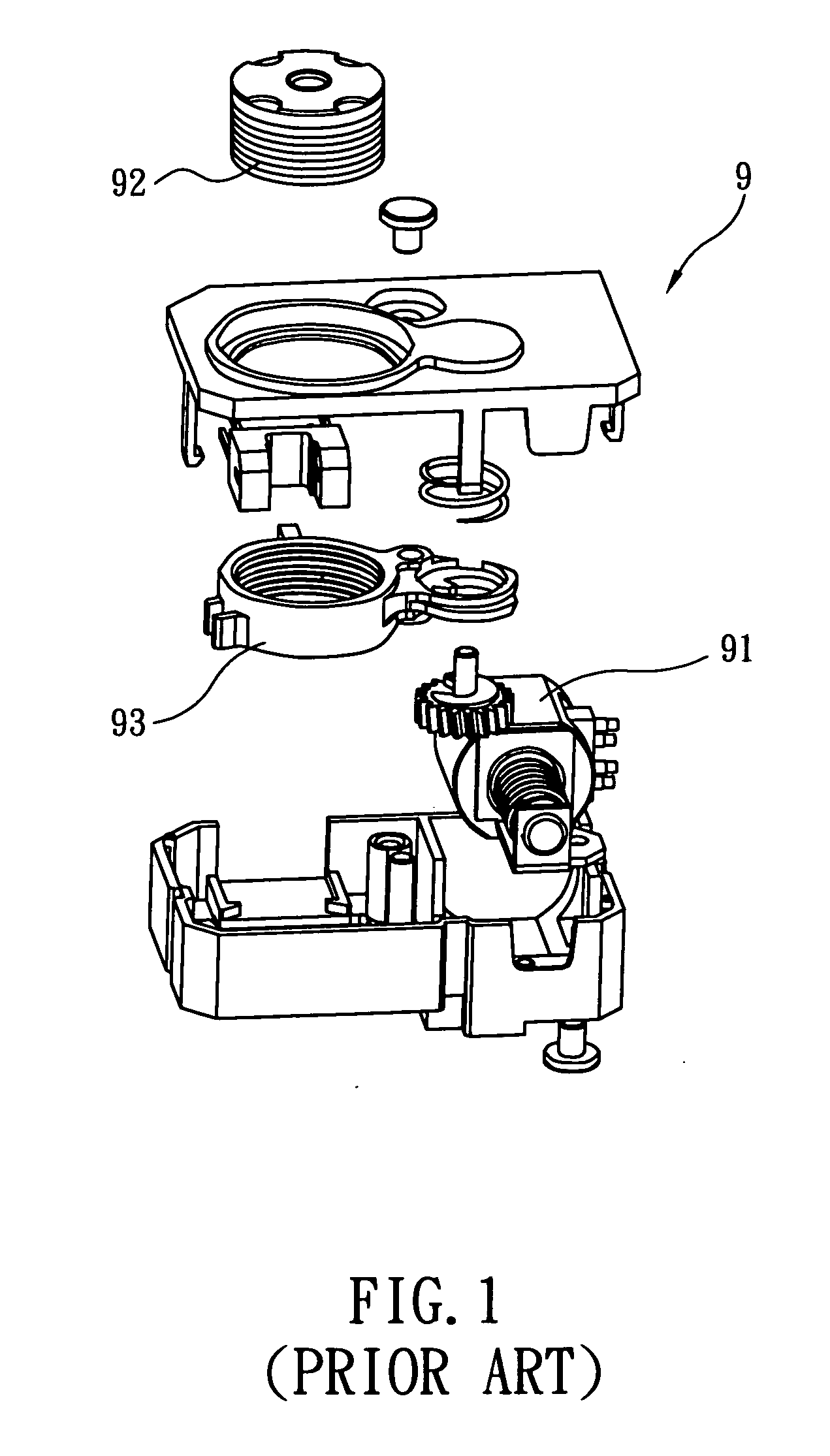
a driving device and electromagnetic technology, applied in the direction of dynamo-electric components, dynamo-electric machines, instruments, etc., can solve the problems of significant power consumption, disadvantaged focusing mechanism b>9/b>, elevated cost, etc., and achieve the effect of reducing the number of components and simplifying the overall structur

Active Publication Date: 2012-02-02
TDK TAIWAN
View PDF1 Cites 76 Cited by
  • Summary
  • Abstract
  • Description
  • Claims
  • Application Information

AI Technical Summary

Benefits of technology

[0008]The first objective of the present invention is to provide an electromagnetic lens driving device based on the principle of electromagnetic induction, wherein electric current is applied to an annular coil to drive a lens module into linear axial displacement within a receiving space. As the conventional stepper motor is omitted, the number of components is reduced, the lens driving device downsized, and the overall structure simplified.

Problems solved by technology

Therefore, the focusing mechanism 9 is disadvantaged by a complex mechanical structure, a complicated assembly process, a large volume, an elevated cost, significant power consumption, and consequently a high selling price.
Nevertheless, the conventional stepper motor-driven zoom lens cannot be further downsized and therefore prevents the overall products from getting thinner and lighter.

Method used


Image

  • Electromagnetic lens driving device
  • Electromagnetic lens driving device
  • Electromagnetic lens driving device

Examples


Embodiment Construction

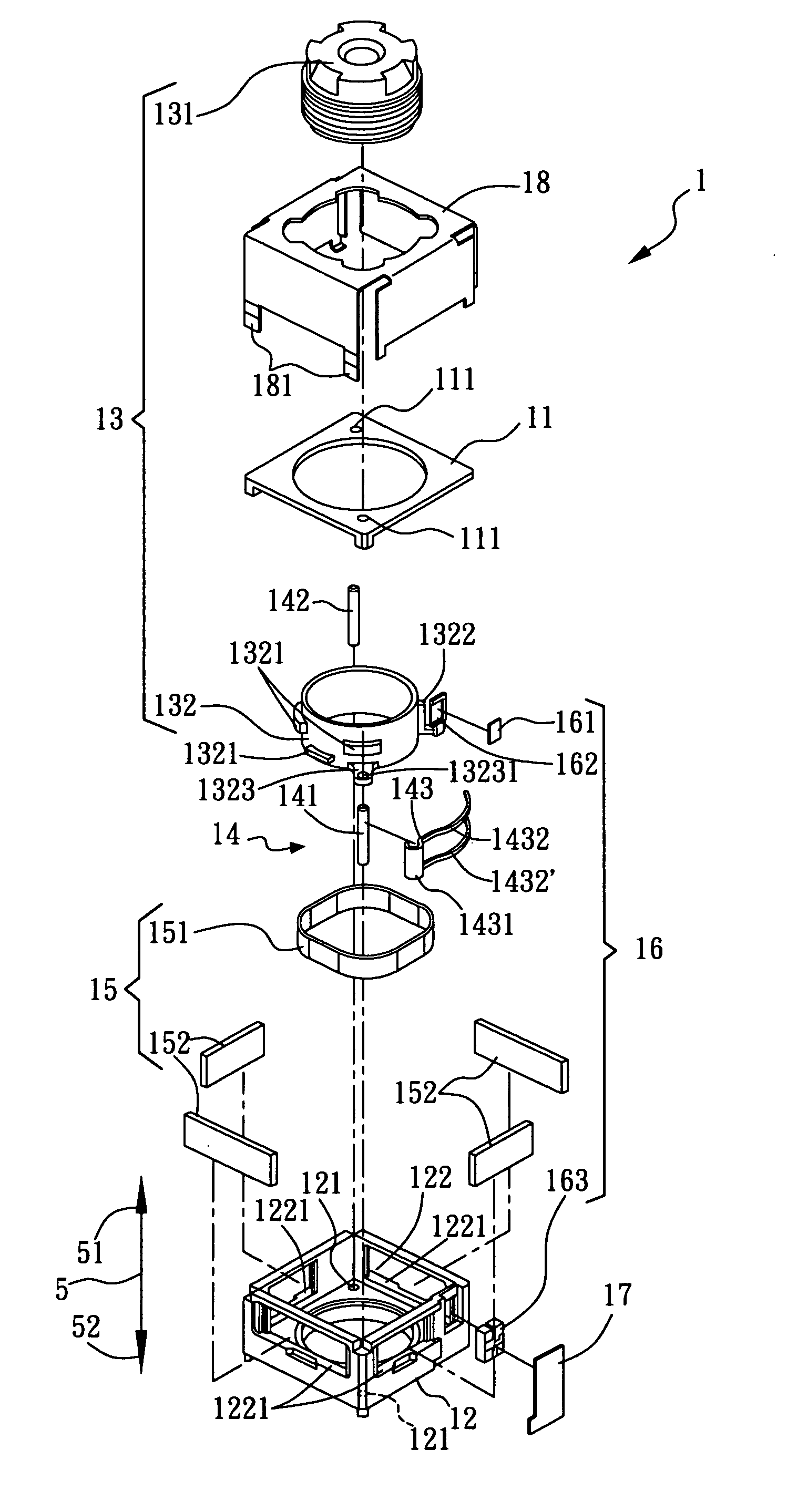
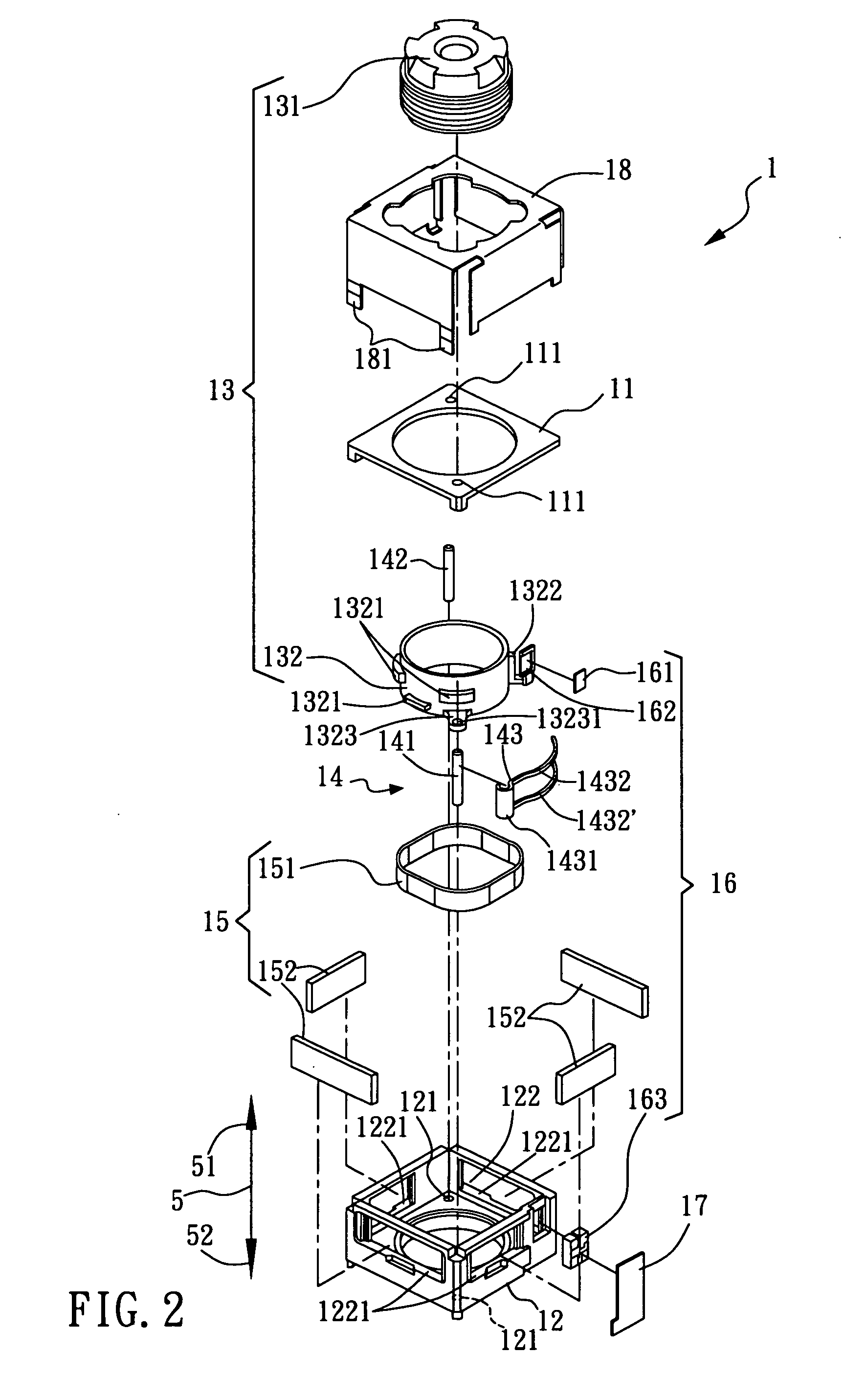
[0033]Referring to FIG. 2, FIG. 3, FIG. 4A, and FIG. 4B, an electromagnetic lens driving device 1 defines a central axis 5 and includes an upper cover 11, a casing 12, a lens module 13, a positioning structure 14, an electromagnetic driving module 15, a sensing module 16, a circuit board 17, and a shell 18. The central axis 5 has two axial directions, namely a front direction 51 and a rear direction 52.

[0034]The upper cover 11 is a hollow annular cover, and the casing 12 is a hollow seat. When connected to each other, the upper cover 11 and the casing 12 substantially form a hollow housing structure that defines a receiving space 122 therein. The receiving space 122 thus defined in the casing 12 has a periphery provided with a plurality of evenly arranged receiving slots 1221.

[0035]The lens module 13 is located in the receiving space 122 and centered on the central axis 5. When driven by the electromagnetic driving module 15, the lens module 13 is moved upward or downward along the ...


PUM


Abstract

An electromagnetic lens driving device includes a casing, a lens module, a positioning structure, and an electromagnetic driving module. The lens module is provided in a receiving space defined in the casing. The positioning structure, which is connected between the lens module and the casing, is configured to limit the lens module within the receiving space and generate a frictional force. The electromagnetic driving module is provided in the receiving space and corresponds in position to the lens module. When supplied with electricity, the electromagnetic driving module generates a magnetic force that drives the lens module to move along a central axis. Once the electricity is cut off, the lens module is fixed in position and prevented from moving freely by the frictional force of the positioning structure; hence, the electromagnetic lens driving features economical use of electricity.

Description

BACKGROUND OF INVENTION[0001]1. Field of the Invention[0002]The present invention relates to a lens driving device and, more particularly, to an electromagnetic lens driving device which includes: an electromagnetic driving module for driving a lens module to move within a casing, and a positioning structure for securing the lens module in position within the casing when power is cut off.[0003]2. Description of the Prior Art[0004]Please refer to FIG. 1 for an exploded perspective view of a conventional zoom lens. The conventional zoom lens uses a mechanical transmission-type focusing mechanism 9 that includes not only a multitude of transmission elements, but also a high-cost, high-precision driving element 91 (e.g., a stepper motor, ultrasonic motor, piezoelectric actuator, etc.) as a power source for driving a lens mount 93 mounted with a lens set 92. Therefore, the focusing mechanism 9 is disadvantaged by a complex mechanical structure, a complicated assembly process, a large vol...

Claims


Application Information

Patent Timeline
Patent Type & Authority Applications(United States)
IPC IPC(8): G02B7/04
CPCH02K41/0356G02B7/08
Inventor HU, CHAO CHANGWU, FU YUANHUANG, SHIH TING
Owner TDK TAIWAN
Why Eureka
Try Eureka