Display device

a display device and display technology, applied in the field of display devices, can solve the problems of plurality of display images not being provided, display devices cannot feed back a setting, etc., and achieve the effects of reducing the number of components of display devices, increasing the range of display possibilities, and reducing costs

Inactive Publication Date: 2008-07-03
SEMICON ENERGY LAB CO LTD
View PDF40 Cites 76 Cited by
  • Summary
  • Abstract
  • Description
  • Claims
  • Application Information

AI Technical Summary

Benefits of technology

[0014]The present invention increases a communication distance because a battery can be charged up with electric power when the display device utilizing the radio technology of the present invention is in an environment where it can receive a radio signal and the display device does not display an image, and the electric power stored in the battery is utilized in transmitting a radio signal to a data transmitting and receiving device from the display device.
[0016]The present invention can reduce the number of components of a display device utilizing radio technology and can lower cost.
[0017]The present invention increases a range where display is possible even when the display device is at a distance where a display device has not been able to display an image due to a decrease of a signal according to an increase in a distance from a data transmitting and receiving device even if the display device is capable of receiving an radio signal.
[0018]The display device of the present invention can improve the reliability because it is free from degradation of an FPC, a disconnection of a cable, and the like since the display device of the present invention does not need an input / output terminal such as an FPC or a cable for connecting to the display device and inputting an image signal to the display device directly, and can operate using a radio signal.

Problems solved by technology

In Patent Document 1, however, the display device performs one-way reception of the image signal and does not perform transmission thereof.
Therefore, there is a problem that the display device cannot feed back a setting, a display image, or the like which an operator desires, while an image signal transmitter set separately can.
In addition, an image signal transmitter can provide only one kind of image which is set by the image signal transmitter, and a plurality of display images cannot be provided at one time.

Method used


Image

  • Display device
  • Display device
  • Display device

Examples


embodiment mode 1

[0033]The display device of the present invention does not need an input / output terminal such as an FPC, a cable, or the like for connecting to the display device and inputting an image signal to the display device directly, and can operate using a radio signal. A structure of the display device of the present invention is explained hereinafter.

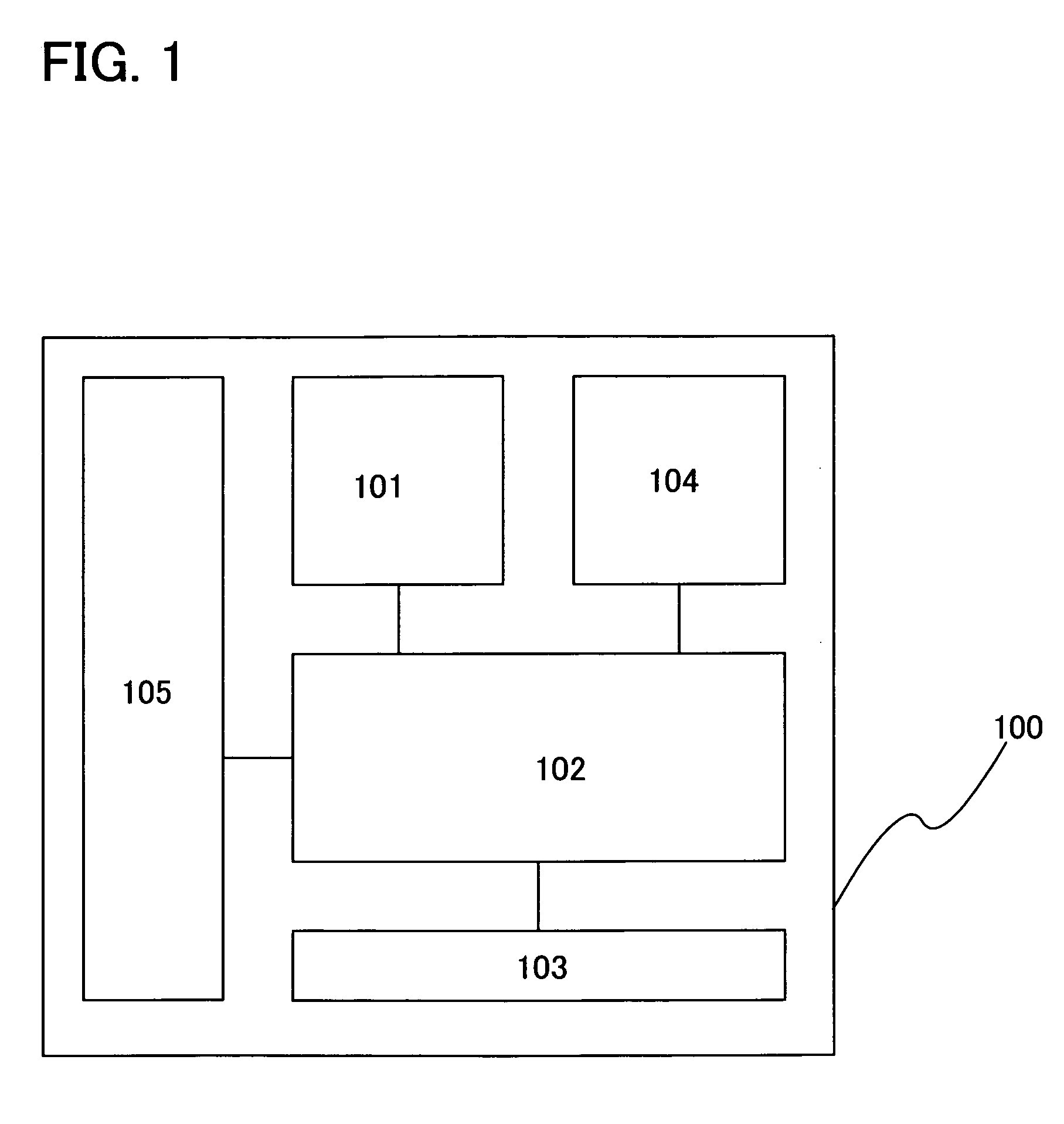
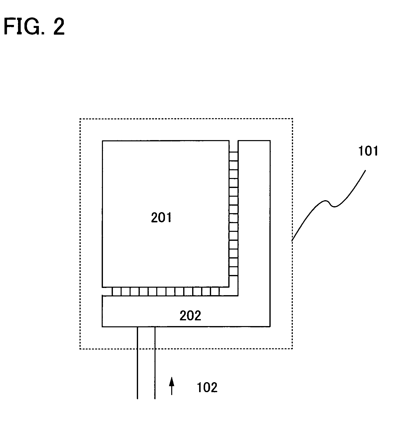
[0034]As shown in FIG. 1, a display device 100 includes a display portion 101, a controller portion 102, an antenna portion 103, a battery portion 104, and a console portion 105.

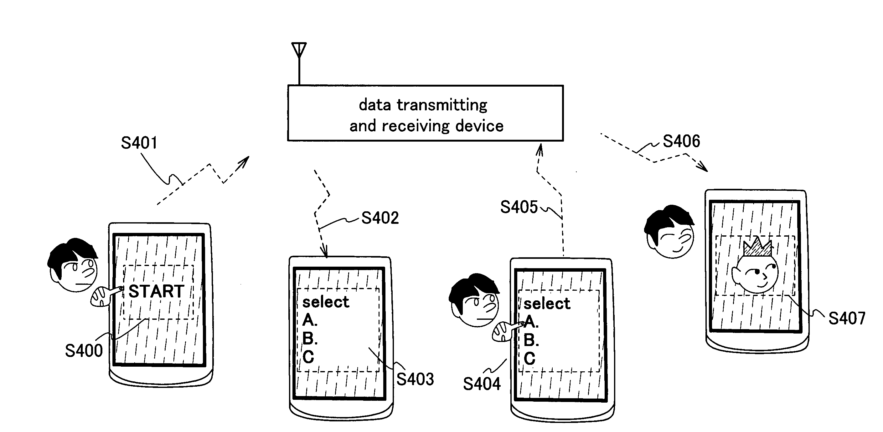
[0035]The display device 100 is supplied with a radio signal 702 from a data transmitting and receiving device 701, as shown in FIG. 7. The display device 100 can be supplied with electric power and receive data by the radio signal 702 from the data transmitting and receiving device 701. The data transmitting and receiving device 701 receives a radio signal 703 which is transmitted from the display device 100 and transmits a radio signal according to the received sign...

embodiment 1

[0108]This embodiment explains an example when each circuit which constitutes the display device of the present invention explained in the above embodiment mode is formed over the identical substrate. Although this embodiment explains a case where the structure of the display device is an active matrix type, the present invention can also be applied to a passive matrix structure. As an example, this embodiment explains a display device in which an electrophoretic display element, so-called electronic paper is used for a display element, with reference to a top view (FIG. 8A) and a cross-sectional view (FIG. 8B).

[0109]As shown in FIG. 8A, a display portion 801, a drive circuit region 802a which is a scanning line drive region, a drive circuit region 802b which is a signal line drive region, a controller portion 803, a battery portion 804, and an antenna portion 805 are provided over a substrate 800. In this embodiment, the display portion 801 is explained as a display portion of a to...

embodiment 2

[0135]This embodiment explains uses of the display device of the present invention. The display device of the present invention can be used by being provided for or incorporated in an object such as a certificate (a driver's license, a resident card, or the like), a recording medium (DVD software, a video tape, or the like), a vehicle (a bicycle or the like), a personal belonging (a bag, glasses, or the like), a human body, clothing, a daily commodity, or a product such as an electronic device. The electronic device includes a liquid crystal display device, an EL display device, a television unit (also referred to simply as a “TV”, a “TV receiver”, or a “television receiver”), a cellular phone, and the like.

[0136]This embodiment explains an application of the present invention and an example of a commercial product to which the application article is attached with reference to FIGS. 9A to 9C.

[0137]FIG. 9A shows a label-formed display device 3001. Providing the display device 3001, w...


PUM

PropertyMeasurementUnit
temperatureaaaaaaaaaa

Abstract

An object of the present invention is to provide a display device which does not need an input / output terminal such as an FPC or a cable for connecting to the display device and inputting an image signal to the display device directly, and can provide a setting, a display image, and the like which an operator desires. A display device of the present invention includes a display portion, a console portion to operate or input from the exterior, an antenna portion to transmit and receive a radio signal, a controller portion to control a signal input into the console portion and a signal for being transmitted or received in the antenna portion, and a battery portion to convert the radio signal received in the antenna portion into electric power and retain the electric power for driving the display portion.

Description

BACKGROUND OF THE INVENTION[0001]1. Field of the Invention[0002]The present invention relates to a display device for displaying an image, in particular, to a display device to carry out data communication utilizing radio technology.[0003]2. Description of the Related Art[0004]With the coming of advanced information society, demands for computers, navigation systems, personal digital assistants, information communication devices, and composite products thereof have been increasing in recent years. Thin and light-weight display devices with low power consumption are suitable for display systems of these products, and liquid crystal display devices or display devices utilizing self-luminous electro-optic elements such as light-emitting EL elements or LEDs are used.[0005]Such a display device has a built-in power supply for drive, and a method has been used in which an image signal is supplied externally by a flexible printed circuit (an FPC) or a cable.[0006]However, problems such as ...

Claims


Application Information

Patent Timeline
Patent Type & Authority Applications(United States)
IPC IPC(8): G09G5/00G02F1/167G06F1/16G09F9/00G09F9/37G09G3/20G09G3/34
CPCG06F3/14G06F3/147G09G3/2092G09G2370/16G09G2330/02G09G2380/06H04N5/66G09G3/2096G09G2380/04H04N5/44
Inventor HATA, YUKIKOYAMA, JUNNAGATSUKA, SHUHEIKIMURA, AKIHIRO
Owner SEMICON ENERGY LAB CO LTD
Why Eureka
Try Eureka