
Lens unit and compact image pickup module

Inactive Publication Date: 2005-08-04
FUJIFILM CORP +1
View PDF0 Cites 70 Cited by
  • Summary
  • Abstract
  • Description
  • Claims
  • Application Information

AI Technical Summary

Benefits of technology

[0022] A first object of the present invention is to solve the problems of the conventional techniques described above, and to provide a compact image pickup module applied to a mobile telephone with a photographing function, an inexpensive / compact digital camera, or the like, where a simple construction is used, appropriate focusing is performed, and it is possible to prevent optical axis inclination with reliability, and to provide a compact image pickup module where the number of components is reduced and a macro photographing function with a simple construction is realized.
[0023] Also, a second object of the present invention is to solve the problems of the conventional techniques described above, and to provide a compact image pickup module applied to a mobile telephone or a PDA with a photographing function, an inexpensive / compact digital camera, or the like, where a simple construction is used and it is possible to appropriately position a light receiving portion of an image pickup element, such as a CCD sensor, with respect to the optical axis of an imaging lens by performing positioning of the CCD sensor in an x-y direction (direction orthogonal to the optical axis of the imaging lens) through simple work.
[0024] Further, a third object of the present invention is to solve the problems of the conventional techniques described above, and to provide a lens unit suitably applied to a compact image pickup module or the like applied to a mobile telephone with a photographing function or the like and produced by incorporating multiple lenses into a lens-barrel, where a simple construction is used, the optical axes of the lenses are set so as to coincide with each other, and it is possible to prevent displacements between the optical axes of the lenses.

Problems solved by technology

It is difficult to realize an imaging lens (lens unit) having such resolving power using a single lens.
When the optical axis is inclined, an imaging surface is also of course inclined, so a photographed image is not appropriately formed on the light receiving surface of the CCD sensor and image quality is degraded.
Therefore, when the optical axis is inclined, even if the degree of the inclination is small, there occurs extremely significant image quality degradation.
Consequently, when the positioning of the CCD sensor in the x-y direction is performed in the manner described above, it is impossible to perform the positioning of the CCD sensor in the x-y direction accurately so that the optical axis of the imaging lens and the center of the light receiving portion coincide with each other.
Such CCD sensor incorporation work takes a very long time and is a factor of a reduction in productivity of the compact image pickup module and an increase in manufacturing cost thereof.
Therefore, when displacements (hereinafter referred to as “inter-lens eccentricity”) between the optical axes of the lenses 100 occur, even if the degrees of the displacements are small, there occurs extremely significant image quality degradation.

Method used


Image

  • Lens unit and compact image pickup module
  • Lens unit and compact image pickup module
  • Lens unit and compact image pickup module

Examples


Embodiment Construction

[0065] Hereinafter, a compact image pickup module and a lens unit according to the present invention will be described in detail based on preferred embodiments illustrated in the accompanying drawings.

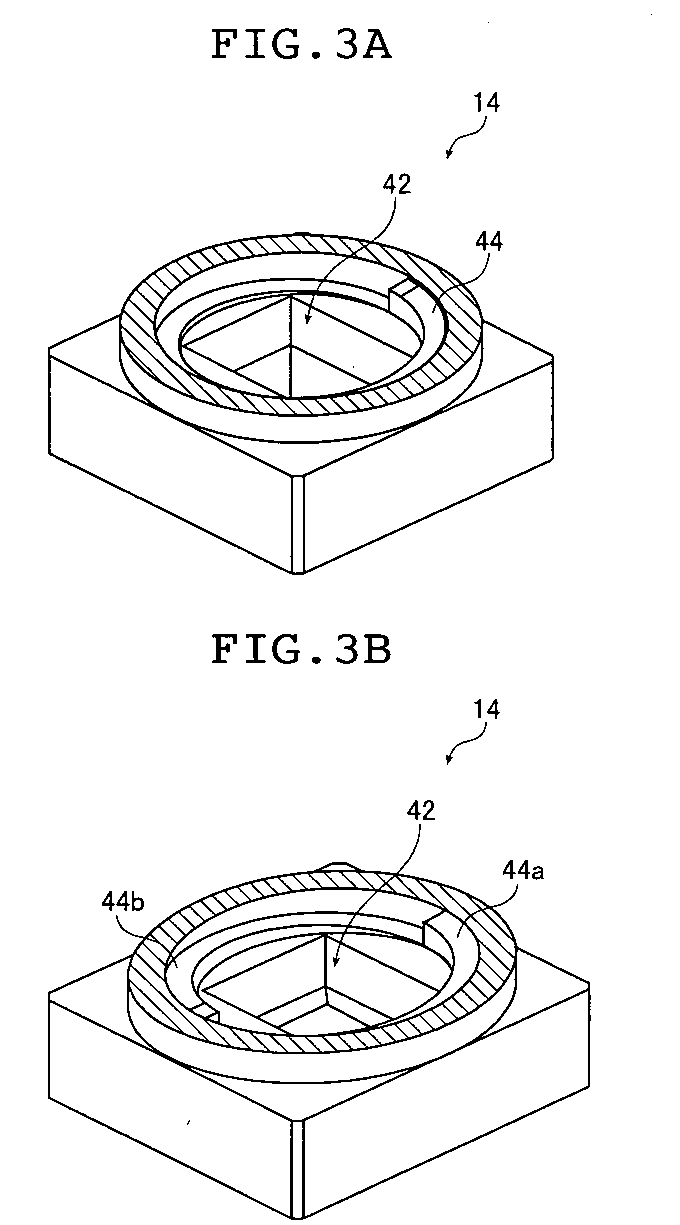
[0066] First, a compact image pickup module according to the first and third aspects of the present invention and a lens unit according to the fourth aspect of the present invention will be described with reference to FIGS. 1 to 6B.

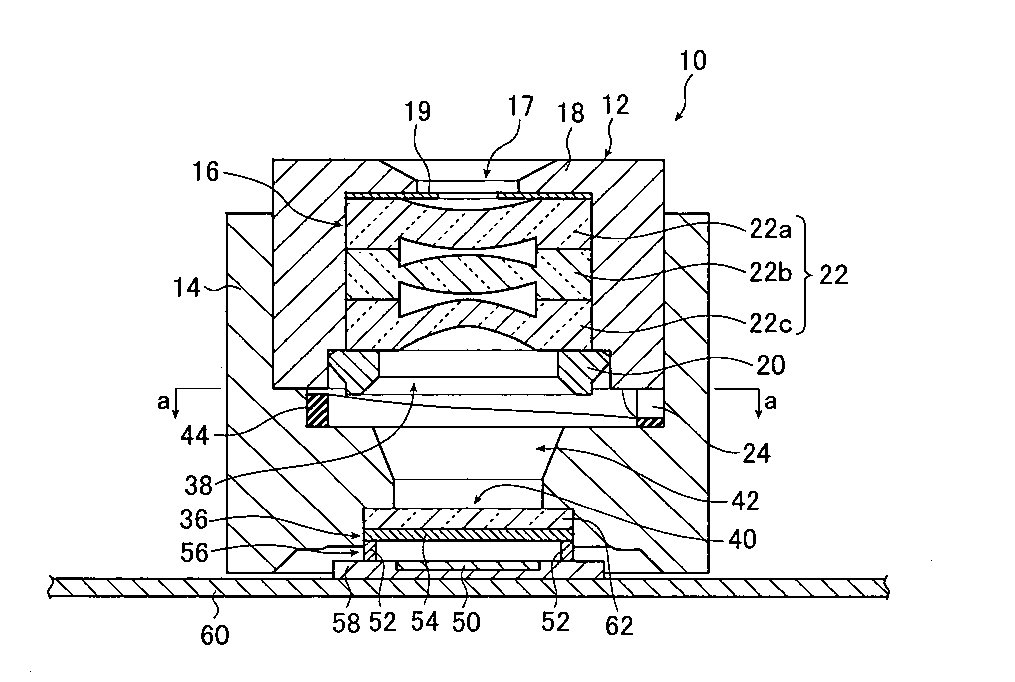
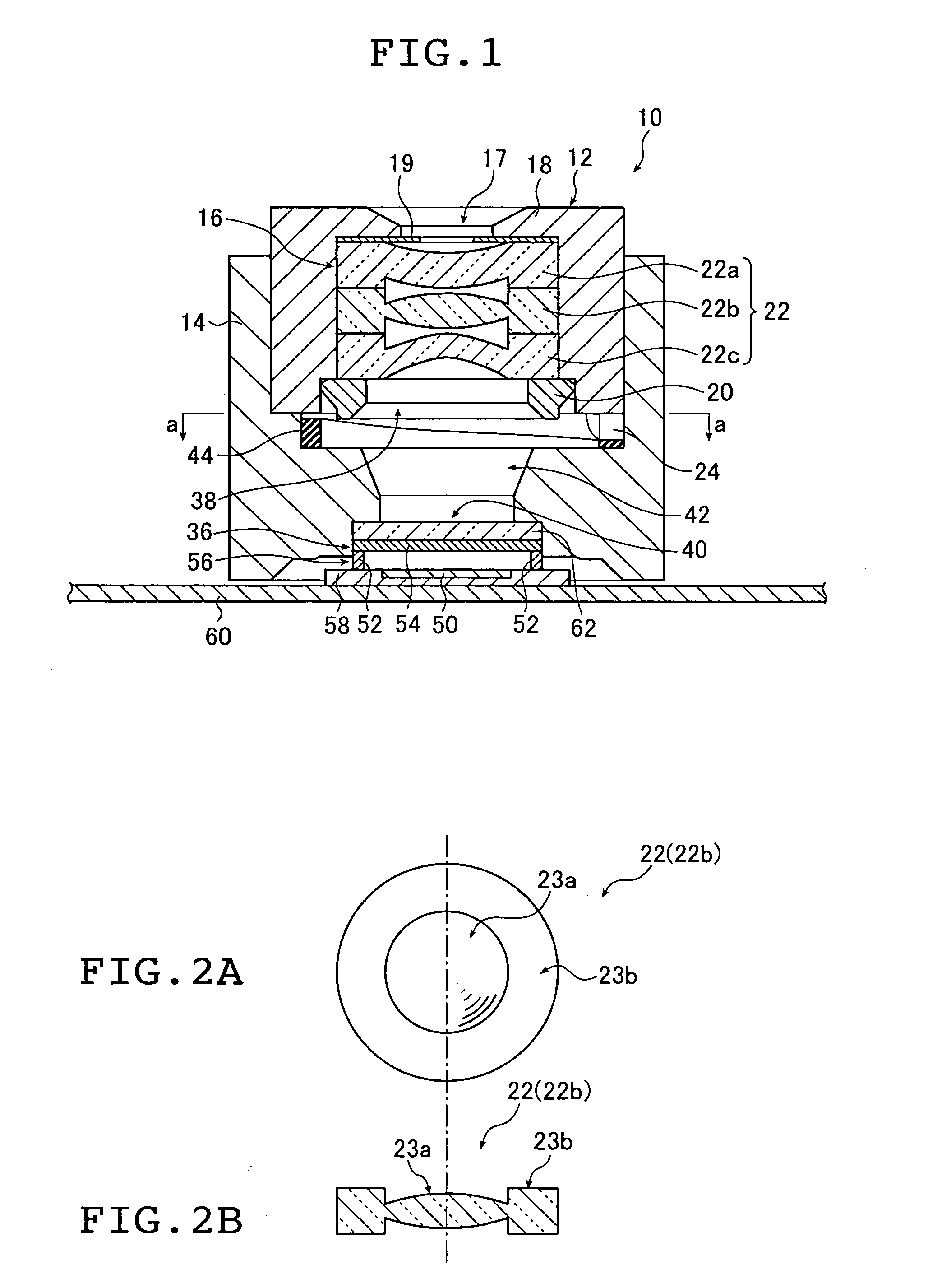
[0067]FIG. 1 is a schematic cross-sectional view of an embodiment of the compact image pickup module according to the first and third aspects of the present invention. Note that FIG. 1 is a cross-sectional view taken by cutting the compact image pickup module along a plane containing the optical axis of an imaging lens (hereinafter simply referred to as “optical axis”). Here, the compact image pickup module shown in FIG. 1 uses the lens unit according to the fourth aspect of the present invention, although the present invention is not limited to this and t...


PUM


Abstract

The compact image pickup module includes an imaging lens, a lens-barrel holding the imaging lens, an image pickup element, an image pickup element holder holding the pickup element and into which the barrel is fitted so as to be rotatable about an optical axis of the imaging lens and movable in a direction of the optical axis, a cylindrical cam having as an upper or a lower surface thereof, an annular cam surface whose center is set at the optical axis and being formed in one of the barrel and the element holder and an abutment member being abutted against the cam surface under a state where the barrel is fitted into the element holder and formed in the other. After focusing is performed through relative rotation of the barrel and the element holder, the barrel and the element holder are fixed to each other. The lens unit includes the barrel and the imaging lens having multiple lenses held by the barrel.

Description

[0001] This application claims priority on Japanese patent applications No. 2004-23663, No. 2004-33571, No. 2004-35020 and No. 2004-53878, the entire contents of which are hereby incorporated by reference. BACKGROUND OF THE INVENTION [0002] The present invention relates to a compact image pickup module that is attached to a mobile telephone or a PDA with a photographing function or the like, and a lens unit suitable for a compact image pickup module or the like, and more specifically to a compact image pickup module that is capable of performing appropriate focusing, preventing inclination of the optical axis of an imaging lens with respect to an image pickup element such as a CCD sensor, and performing alignment of the image pickup element such as a CCD sensor with ease, a compact image pickup module where macro photographing is realized with a simple mechanism, and a lens unit that includes multiple lenses and is capable of preventing displacements between the optical axes of the ...

Claims


Application Information

Patent Timeline
IPC IPC(8): G02B7/02G02B13/16G02B15/14H04N5/225
CPCG02B13/16H04N5/2254H04N5/2253H01L27/14632H01L27/14806H04N23/54H04N23/55
Inventor YE, ZHIJINWATANABE, SEIICHIYAMAMOTO, KIYOFUMI
Owner FUJIFILM CORP
Learn More