Ceiling fan blade

a ceiling fan and blade technology, applied in the field can solve the problems of limited wind that can be produced, radial arrangement of ceiling fan blades occupying much installation space, and still some defects need to be improved, so as to achieve the effect of increasing wind pressure and producing more wind

Active Publication Date: 2005-06-16
PAN AIR ELECTRIC
View PDF7 Cites 10 Cited by
  • Summary
  • Abstract
  • Description
  • Claims
  • Application Information

AI Technical Summary

Benefits of technology

[0008] The primary object of the present invention is to provide a ceiling fan blade capable of producing full wind pressure and much wind, on the surface of the ceiling fan blade is formed a front wind receiving surface and a rear wind receiving surface, wherein a tangent angle of the rear wind receiving surface is greater than that of the front rear wind receiving surface, the two wind receiving surfaces can effectively increase the wind pressure and produce more wind.
[0009] The secondary object of the present invention is to provide a ceiling fan blade capable of producing full wind pressure and much wind, wherein a wavy wind guide surface is formed between the two wind receiving surfaces, with this wavy wind guide surface sinuous flow can be substantially reduced when the blade is rotating.

Problems solved by technology

Conventional ceiling fan blades are normally arranged on a motor in a radial way, and the ceiling fan blades are simple plate structure, which has been used for long time, but there are still some defects need to be improved:
First, the radial arranged ceiling fan blades occupy much installation space.
Second, the radial arranged ceiling fan blade is simple plate structured, the wind that it can produce is limited.

Method used


Image

  • Ceiling fan blade
  • Ceiling fan blade
  • Ceiling fan blade

Examples


Embodiment Construction

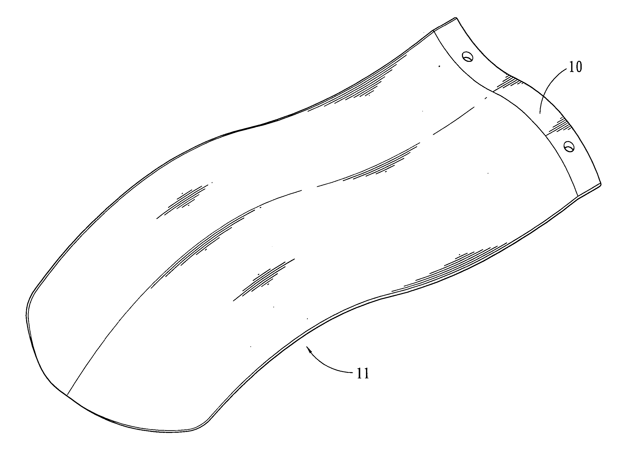
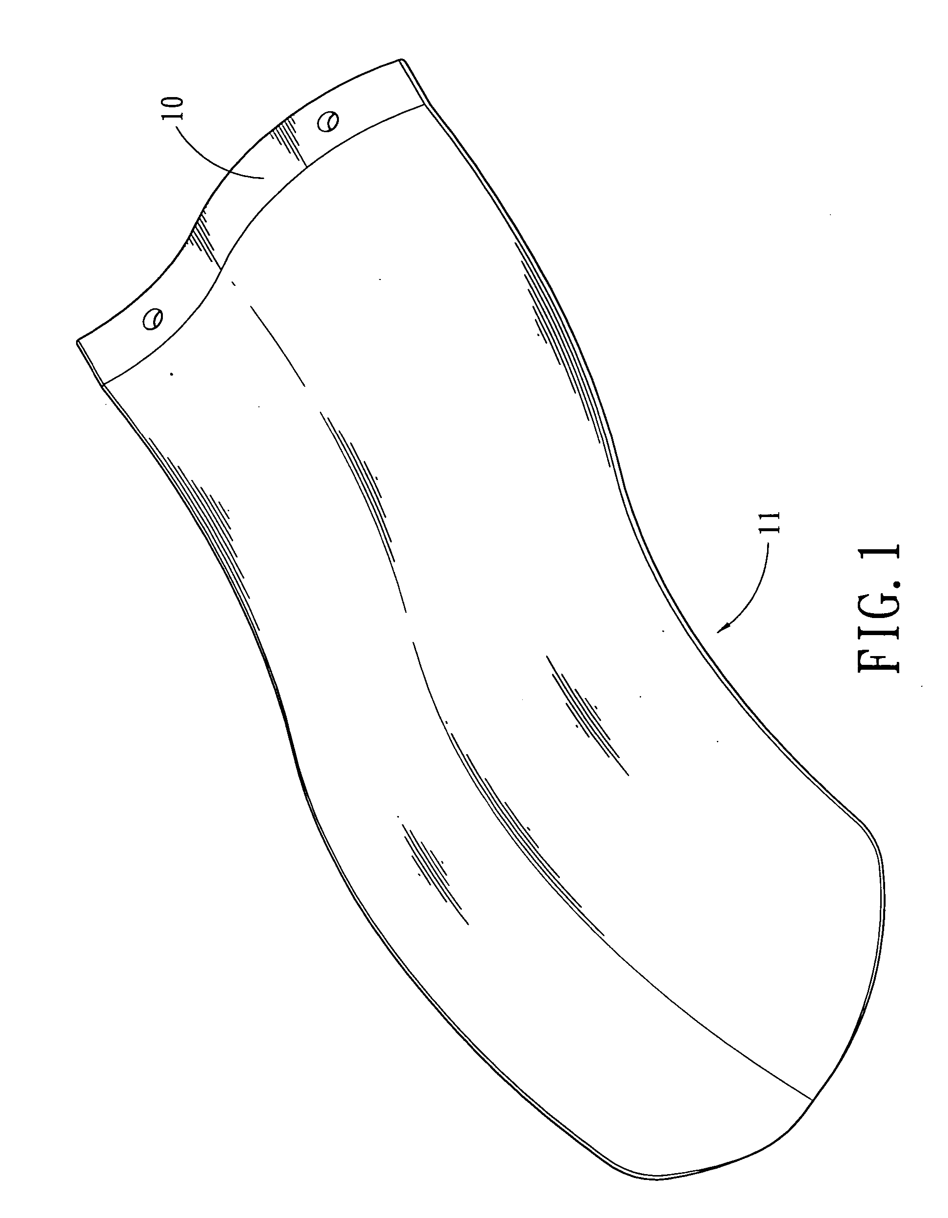
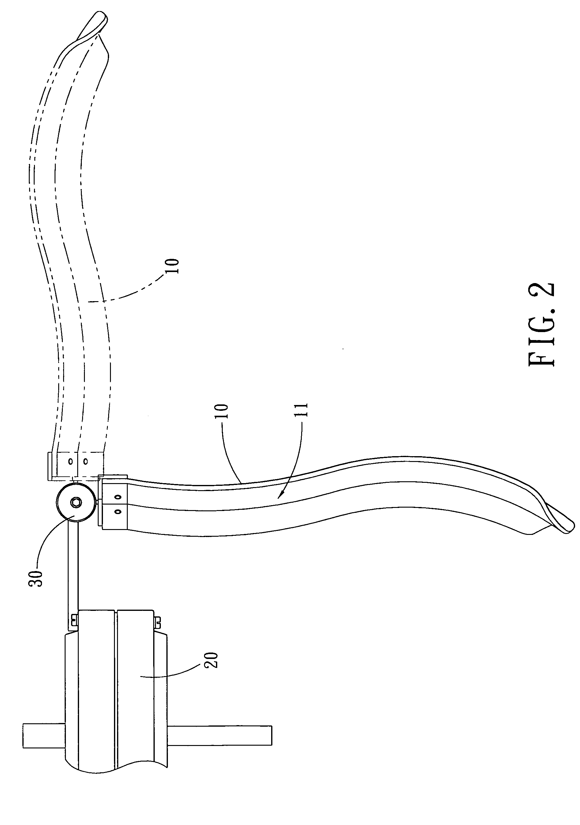
[0019] Referring to FIGS. 1-3, wherein a ceiling fan blade 10 in accordance with the present invention is adapted to be mounted on a lifting mechanism 30 of a motor 20.

[0020] The ceiling fan blade 10 is defined at an upper side of a wind-receiving surface 11 which is parallel to the radial direction with an arc-shaped front wind-receiving surface 111. The front wind-receiving surface 111 forms a tangent angle α with respect to the horizontal line, the tangent angle α is same as that of normal type ceiling fan. Furthermore, next to the front wind receiving surface 111 are sequentially formed a wavy wind guide surface 112 and an arc-shaped rear wind-receiving surface 113 which forms a tangent angle β with respect to the horizontal line. The tangent angle β of the rear wind-receiving surface 113 is greater than the tangent angle α of the front wind-receiving surface 111.

[0021] Referring particularly to FIG. 2, wherein the ceiling fan blade 10 is mounted on the lifting mechanism 30 of...


PUM


Abstract

The present invention relates to a ceiling fan blade capable of producing full wind pressure and much wind. The solution of the present invention is to form a front and a rear wind receiving surfaces on the ceiling fan blade. A tangent angle of the rear wind-receiving surface is bigger than that of the front wind-receiving surface. A wavy wind guide surface is formed between the two wind receiving surfaces. The wavy wind guide surface and the two wind receiving surfaces can effectively increase the wind pressure and the wind; in addition, sinuous flow is substantially reduced when the blade is rotating.

Description

BACKGROUND OF THE INVENTION [0001] 1. Field of the Invention [0002] The present invention relates to a ceiling fan blade capable of producing full wind pressure and much wind. The solution of the present invention is to form a front wind receiving surface, a rear wind receiving surface and a wavy wind guide surface on the ceiling fan blade. With these structures the present invention can effectively increase the wind pressure and the wind; in addition, sinuous flow is substantially reduced when the blade is rotating. [0003] 2. Description of the Prior Arts [0004] Conventional ceiling fan blades are normally arranged on a motor in a radial way, and the ceiling fan blades are simple plate structure, which has been used for long time, but there are still some defects need to be improved: [0005] First, the radial arranged ceiling fan blades occupy much installation space. [0006] Second, the radial arranged ceiling fan blade is simple plate structured, the wind that it can produce is lim...

Claims


Application Information

Patent Timeline
Patent Type & Authority Applications(United States)
IPC IPC(8): F04D25/08F04D29/38
CPCF04D29/384F04D25/088
Inventor LIU, CHING WEN WINSTON
Owner PAN AIR ELECTRIC
Why Eureka
Try Eureka