Blast deflector of fan

A fan diversion and fan technology, which is applied to components, instruments, and electrical digital data processing of pumping devices for elastic fluids, and can solve problems such as reduced heat exchange efficiency, affecting heat dissipation, airflow velocity, and pressure reduction. , to achieve the effect of increasing wind pressure and wind speed

Inactive Publication Date: 2006-07-05
FU ZHUN PRECISION IND SHENZHEN +1
View PDF0 Cites 13 Cited by
  • Summary
  • Abstract
  • Description
  • Claims
  • Application Information

AI Technical Summary

Problems solved by technology

But although this kind of fan guide device can make the airflow concentrate and make it evenly flow to the heating electronic component 240, but when the fan airflow flows through a blunt body, it will form a low pressure zone just behind the blunt body, the hub 210 position of the fan It is a blunt body, so a low-pressure area 230 is formed at the position facing the hub 210 at the air outlet of the fan, which causes the forced airflow generated by the fan to flow back in this area, thereby reducing the flow velocity and pressure of the airflow, and the hub of the fan 210 is directly facing the position of the heating electronic component 240, so the highest heat generation point of the heating electronic component 240 can only be taken away by the return air flow, the heat exchange efficiency is reduced, and the heat dissipation effect is affected

Method used


Image

  • Blast deflector of fan
  • Blast deflector of fan
  • Blast deflector of fan

Examples


Embodiment Construction

[0013] The present invention will be further described below in conjunction with the embodiments with reference to the accompanying drawings.

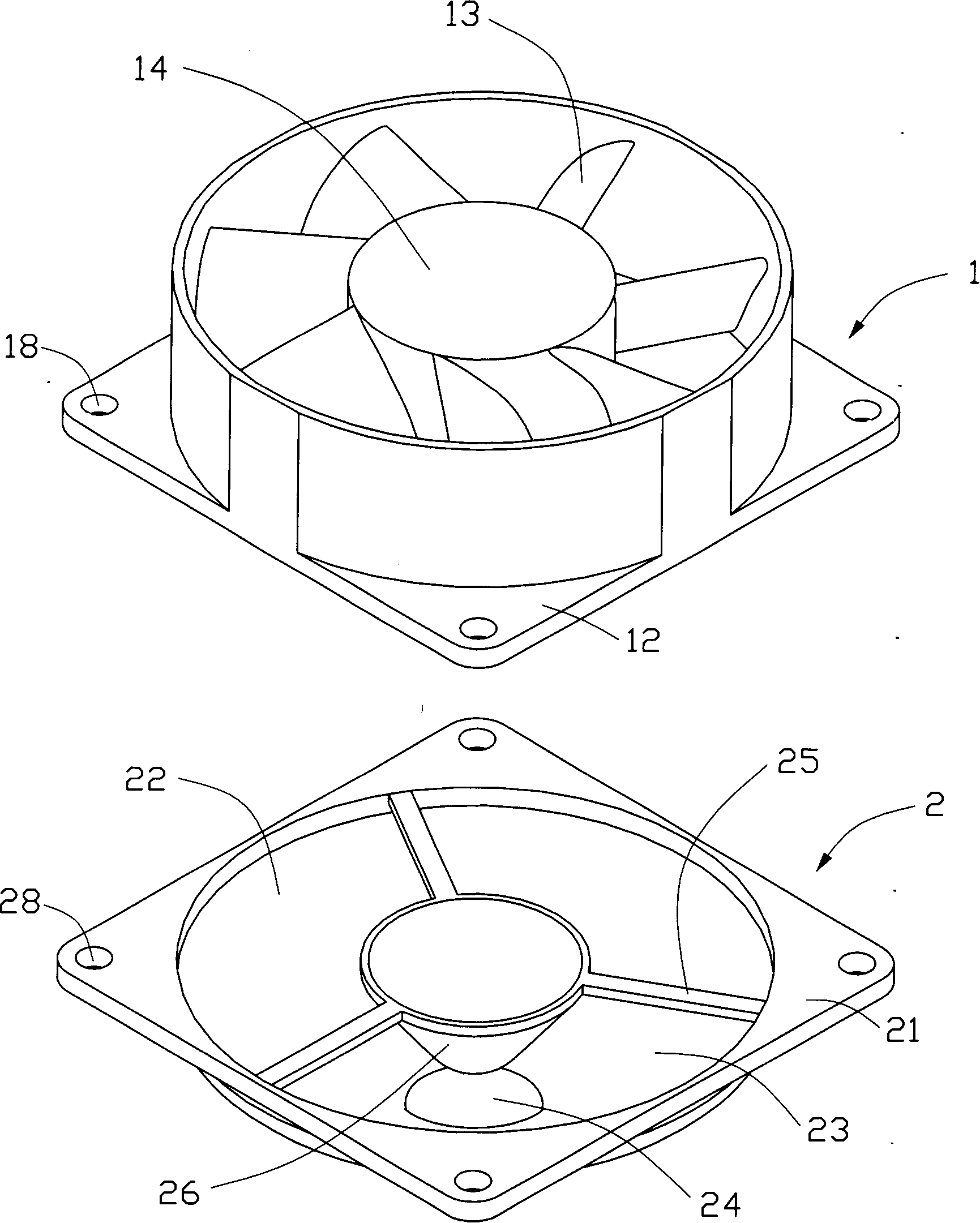
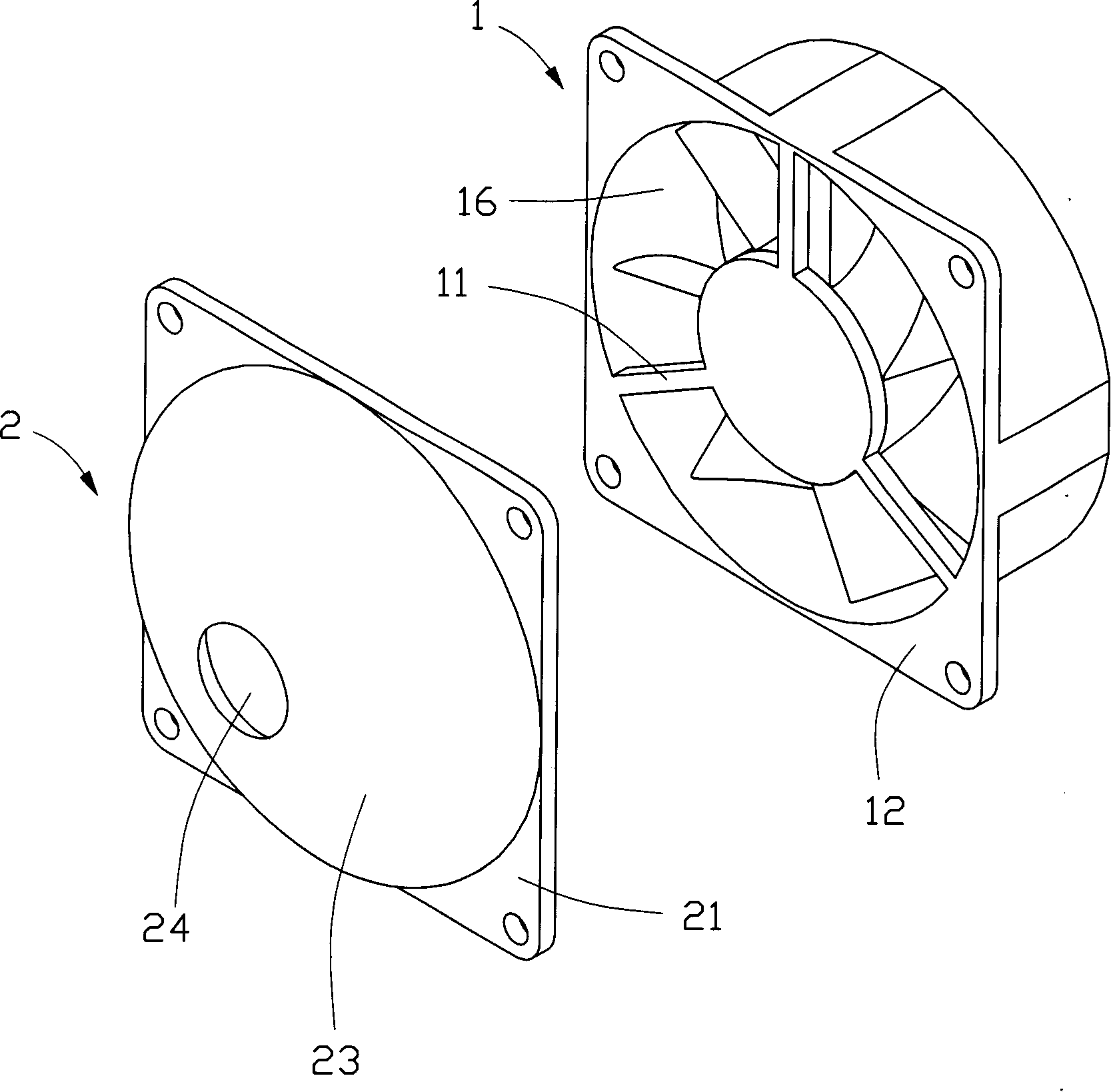
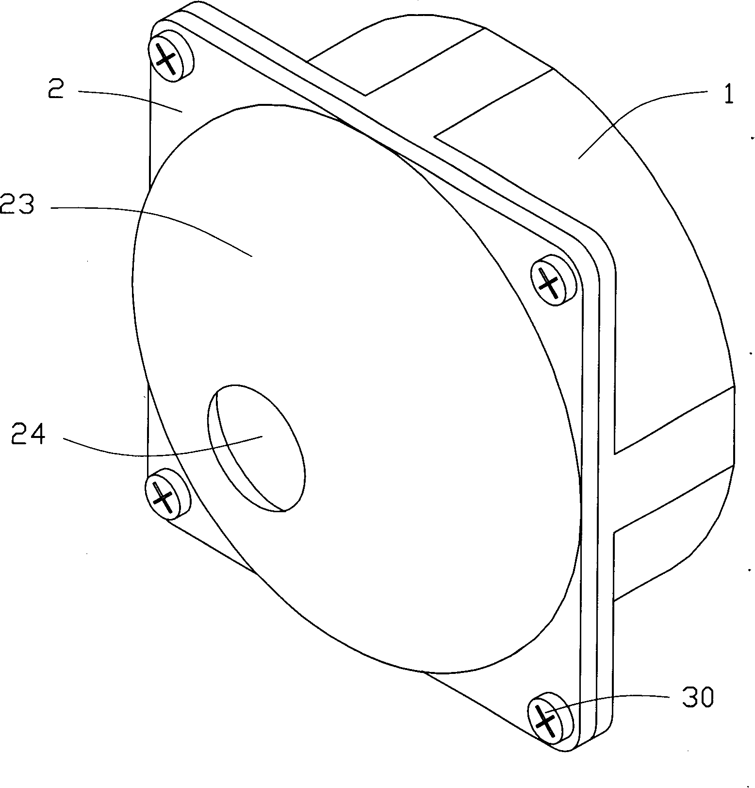
[0014] Such as figure 1 and figure 2 As shown, the fan guide device 2 of the present invention is installed on the air outlet side of the fan 1 .

[0015] The fan 1 includes a fan frame 12, a hub 14 disposed in the fan frame 12, a support frame 11 placed below the hub 14 to support the hub 14, and a plurality of fan blades 13 extending radially outward from the periphery of the hub 14, The support frame 11 is located on the air outlet side 16 of the fan 1 , and the four corners of the fan frame 12 on the air outlet side 16 of the fan 1 are also provided with through holes 18 for fixing parts such as screws 30 to pass through.

[0016] The fan deflector 2 includes a deflector 23 and a guide body 26 inside the deflector 23 . The shroud 23 is roughly in the shape of a nozzle, with a circular cross-section, and a streamlined curved su...


PUM


Abstract

A flow guide device of fan is prepared as setting an air inlet and an air outlet on hollow flow guide case and setting a guiding body in hollow flow guide case, setting said guiding body at air outlet side to directly face to position of hub for preventing generation of low pressure in guiding body region so as to avoid generation of back flow when said flow guide device is used in coordination with fan.

Description

【Technical field】 [0001] The invention relates to a fan device, in particular to a flow guiding device used in conjunction with a fan. 【Background technique】 [0002] With the rapid development of the electronics industry, the processing capacity of electronic components such as the central processing unit is continuously upgraded, and a large amount of heat is generated during operation. If the heat generated is not removed in time, the heat accumulation will cause the temperature to rise and affect the normal operation of electronic components. run. The industry usually installs a heat sink on these heat-generating electronic components to assist in heat dissipation. An axial fan is installed on the heat sink to assemble a heat sink. The fan provides forced airflow to quickly dissipate the heat of the heat sink. [0003] Such as Figure 6 As shown, China Taiwan Patent Publication No. 200403394 discloses a fan device, the air outlet side of the fan frame 220 extends outwar...

Claims


Application Information

Patent Timeline
Patent Type & Authority Applications(China)
IPC IPC(8): F04D29/54G06F1/20
Inventor 詹顺渊刘泰健
Owner FU ZHUN PRECISION IND SHENZHEN
Why Eureka
Try Eureka