Eureka AIR delivers breakthrough ideas for toughest innovation challenges, trusted by R&D personnel around the world.

Radial fan having axial fan blade configuration

a technology of axial fan blades and radial fans, which is applied in the direction of liquid fuel engines, vessel construction, marine propulsion, etc., can solve the problems of poor efficiency, energy loss, and inability to guide airflow out smoothly, so as to increase the work efficiency of the blades, reduce energy loss, and increase the wind pressure on the rotating

Inactive Publication Date: 2006-02-16
DATECH TECH CO LTD
View PDF8 Cites 14 Cited by
  • Summary
  • Abstract
  • Description
  • Claims
  • Application Information

AI Technical Summary

Benefits of technology

"The present invention is a radial fan with axial fan blade configuration that increases wind pressure on rotating blades to reduce energy loss and improve work efficiency. It also reduces noise and lowers working current. The fan comprises a hub with a first set of blades and a second set of blades around the outside of the first set of blades. The second set of blades is rounding at the outside of the first set of blades and has a plurality of gaps between adjacent blades. This structure design increases the wind pressure and reduces energy loss when the blades rotate."

Problems solved by technology

Although the above structure of blades for a fan can be installed into a fan to guide an airflow, when the airflow enters from the top surface of the hub 4 and flows to the blades 42, an air turbulence is brought forth by the airflow and the airflow entered can not be guided out smoothly so that energy loss happens and the efficiency gets worse.
Not only the amount of the airflow will become lesser because of the occurrences of the air turbulence, but also a great amount of noise will be caused on running.
So, the above structure of blades according to the prior art can not fulfill the requirements from the users on actual applications.

Method used


Image

  • Radial fan having axial fan blade configuration
  • Radial fan having axial fan blade configuration
  • Radial fan having axial fan blade configuration

Examples


Embodiment Construction

[0014] The following descriptions of the preferred embodiments are provided to understand the features and the structures of the present invention.

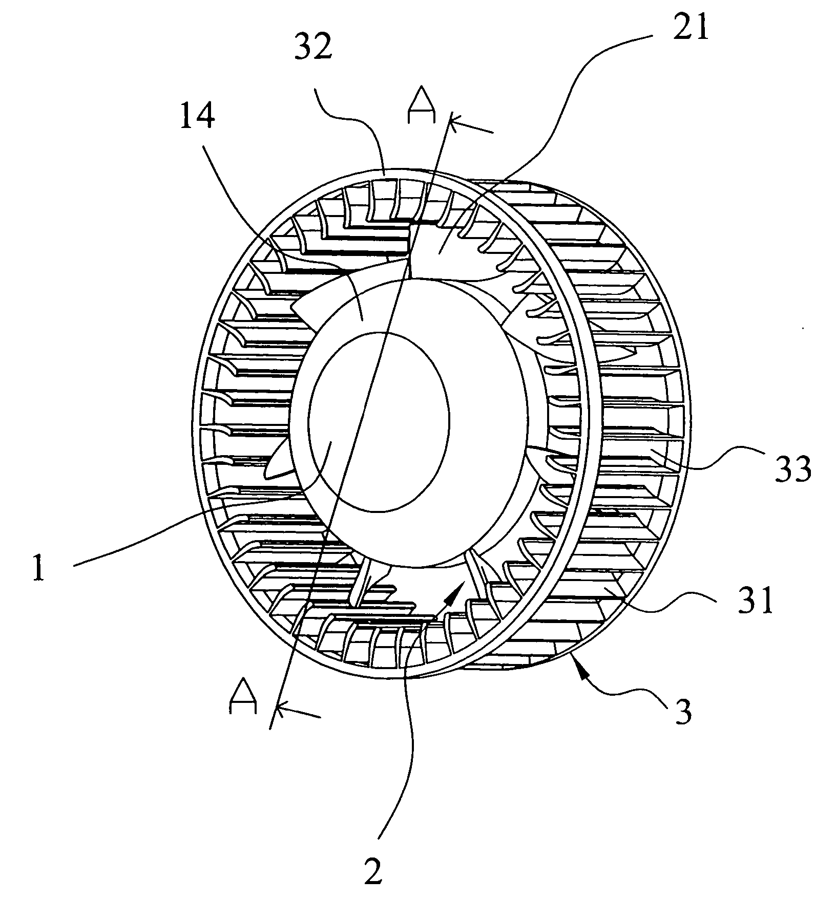
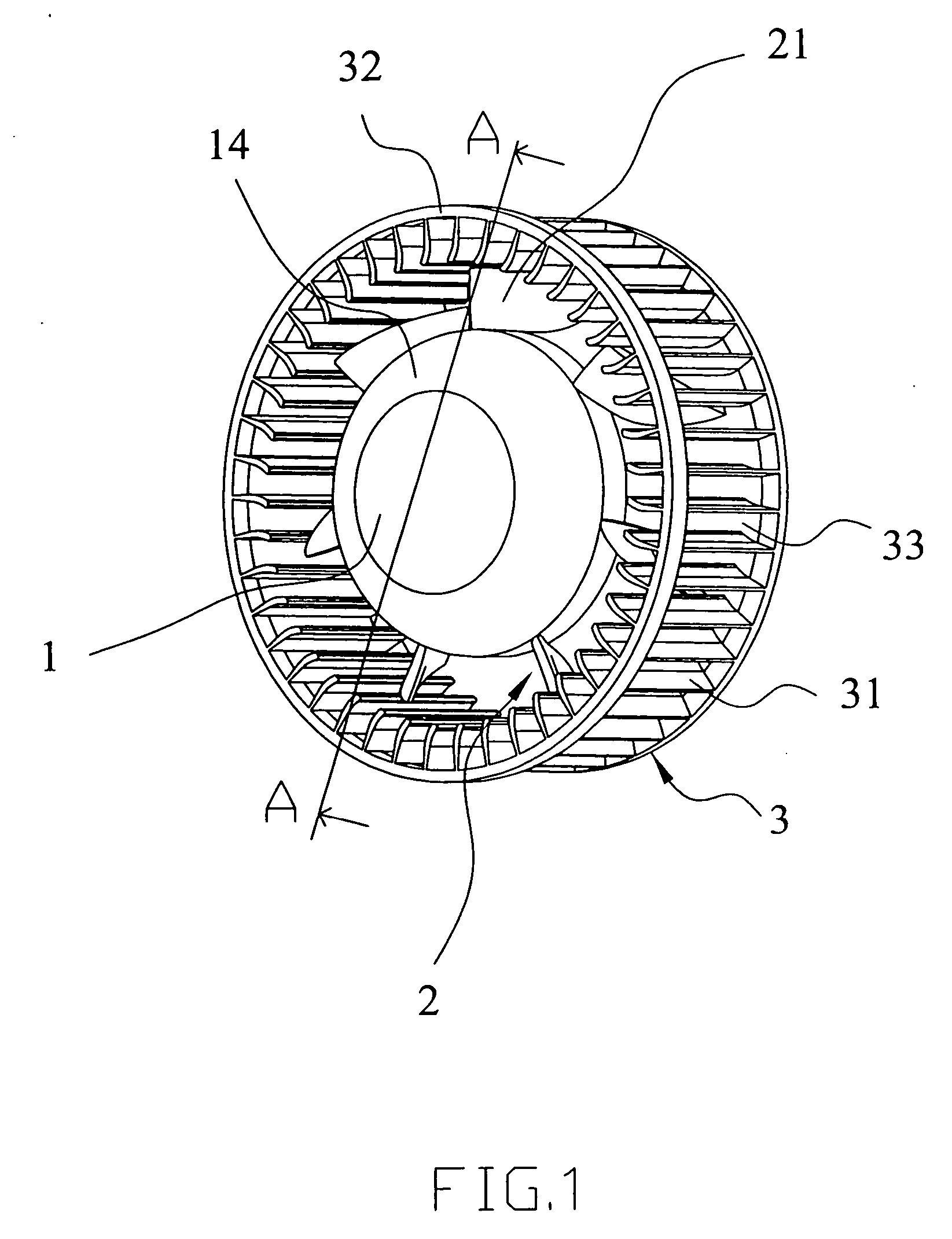
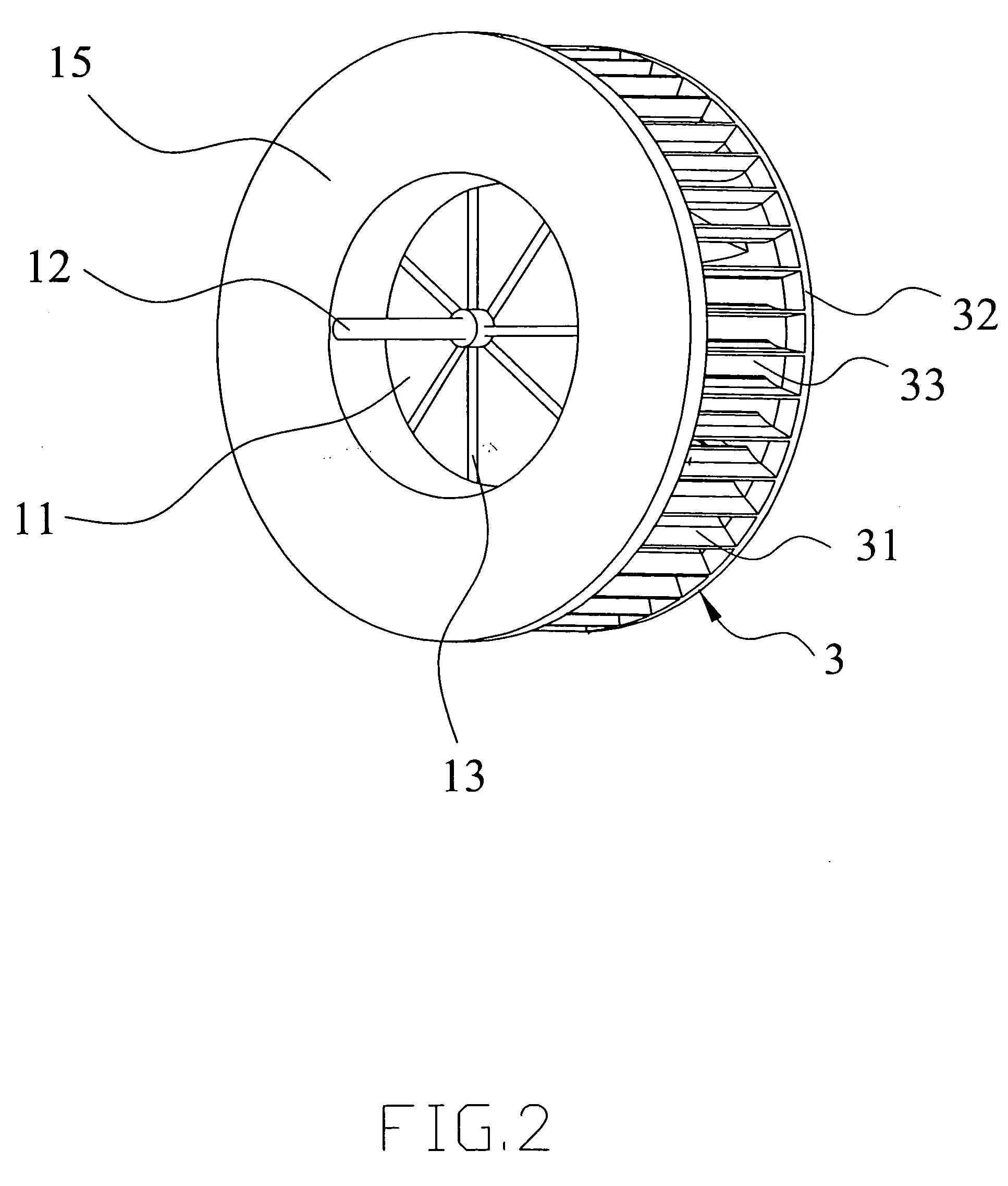
[0015] Please refer to FIG. 1 and FIG. 2, which are a perspective view and another perspective view according to the present invention. As shown in the figures, the present invention is a radial fan having axial fan blade configuration, comprising a hub 1, a first set of blades 2 and a second set of blades 3, wherein, when the structure of the blades rotates, the wind pressure is increased, the energy loss by the blade rotation is reduced and the work efficiency of the blades is raised, while the noise is lessened and the working current is lowered.

[0016] The hub 1 mentioned above comprises a hollow 11; a spindle 12 at the center of the hollow 11; a plurality of ribs 13 in the hollow 11 near the spindle 12 to strengthen the hub structure; a guiding part 14 of a curved surface along the top edge of the hub 1; and an extending part 15 of ...


PUM


Abstract

The present invention is a radial fan having an axial fan blade configuration. The present invention comprises a hub; a first set of blades around the hub; and a second set of blades on the extending part. Therein, the hub comprises a hollow at the center, an axle, a guiding part and an extending part. The gaps are each between every two adjacent blades of the second blade set, having the same distance between every two adjacent gaps. The second set of blades comprises a plurality of blades around outside of the first set of blade and a ring connected with the blades. Accordingly, the structure of the blades may increase the wind pressure, reduce the energy loss by the blade rotation and raise the work efficiency of the blades while the noise is lessened and the working current is lowered.

Description

FIELD OF THE INVENTION [0001] The present invention relates to a radial fan. More particularly, the present invention relates to a radial fan with a structure of blades that can increase the wind pressure, reduce the energy loss caused by the blade rotation and raise the work efficiency of the blades, while the noise is lessened and the working current is lowered. DESCRIPTION OF THE PRIOR ART [0002] As is known, a structure of blades according to the prior art as shown in FIG. 5 and FIG. 6 comprises a hub 4 with a connection part 41 around the edge at the bottom; more than one blades 42 extended up from an end surface of the connection part 41; and more than one gaps 43 between blades 42, wherein a structure of blades for a fan is constructed. [0003] Although the above structure of blades for a fan can be installed into a fan to guide an airflow, when the airflow enters from the top surface of the hub 4 and flows to the blades 42, an air turbulence is brought forth by the airflow an...

Claims


Application Information

Patent Timeline
Patent Type & Authority Applications(United States)
IPC IPC(8): B64C11/00
CPCF04D29/282
Inventor LI, NIEN-LUNTANG, CHIH-WENYEH, YUN-YEUWANG, FU-YIN
Owner DATECH TECH CO LTD
Why Eureka
Eureka Blog
Learn More