Variable stiffness shaft

a shaft and variable technology, applied in the field of variable stiffness shafts, can solve the problems of difficult in vivo retracting of the sheath, affecting the working view or area of the surgeon, and affecting the operation

Inactive Publication Date: 2005-06-16
ETHICON INC
View PDF40 Cites 1376 Cited by
  • Summary
  • Abstract
  • Description
  • Claims
  • Application Information

AI Technical Summary

Problems solved by technology

A second situation involves the positioning of multiple surgical devices at the surgical site, thereby congesting the working view or area for the surgeon.
This problem is particularly acute when using less invasive and minimally invasive surgical techniques, which are becoming more frequently used for their benefits to the patient.
At least one drawback of these devices is that the sheath is difficult to retract in vivo.
Cable tension devices suffer from the problem that they will typically manipulate the operation of the surgical tool carried at the distal end of the flexible shaft in the process of stiffening the shaft.

Method used


Image

  • Variable stiffness shaft
  • Variable stiffness shaft
  • Variable stiffness shaft

Examples


first embodiment

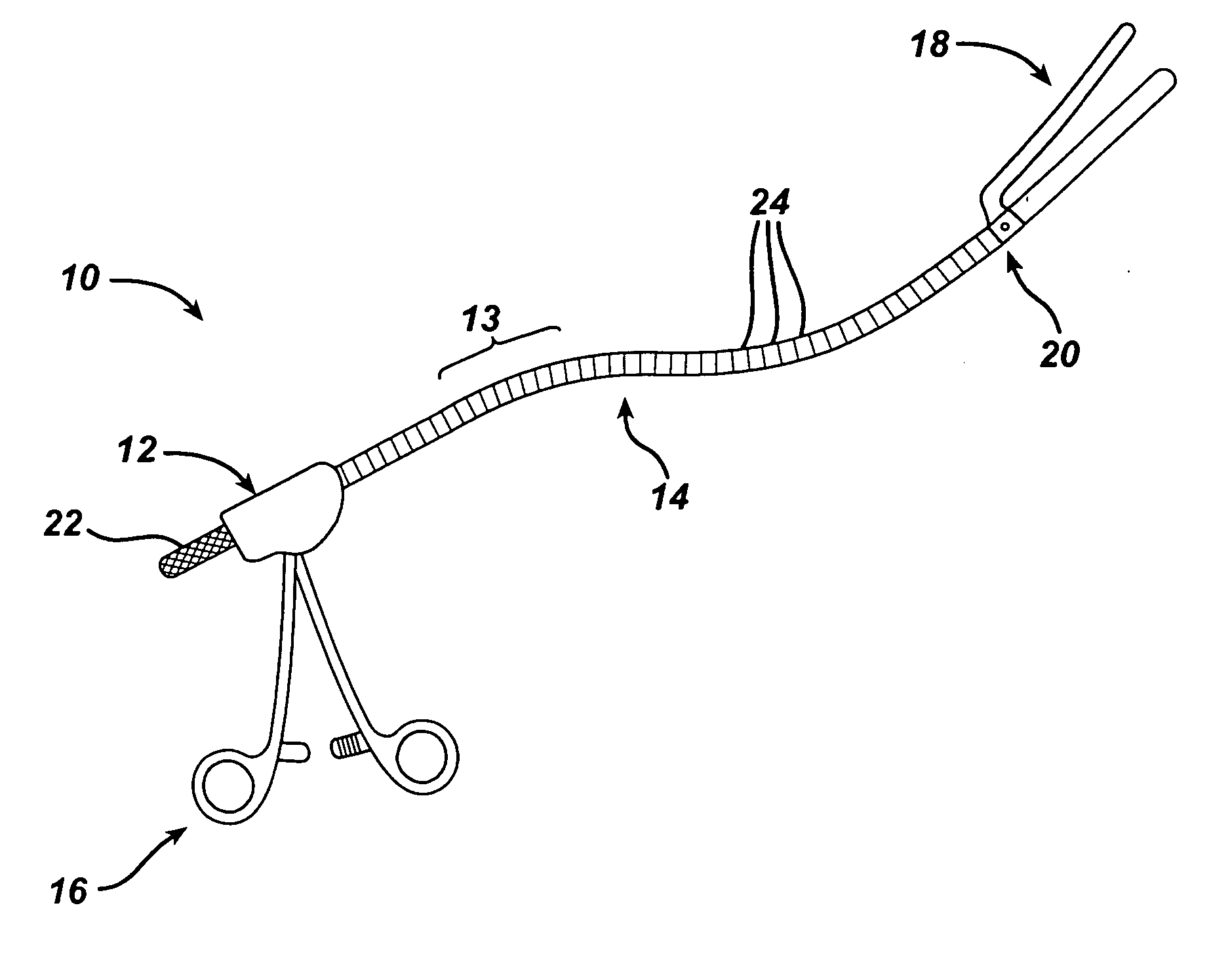
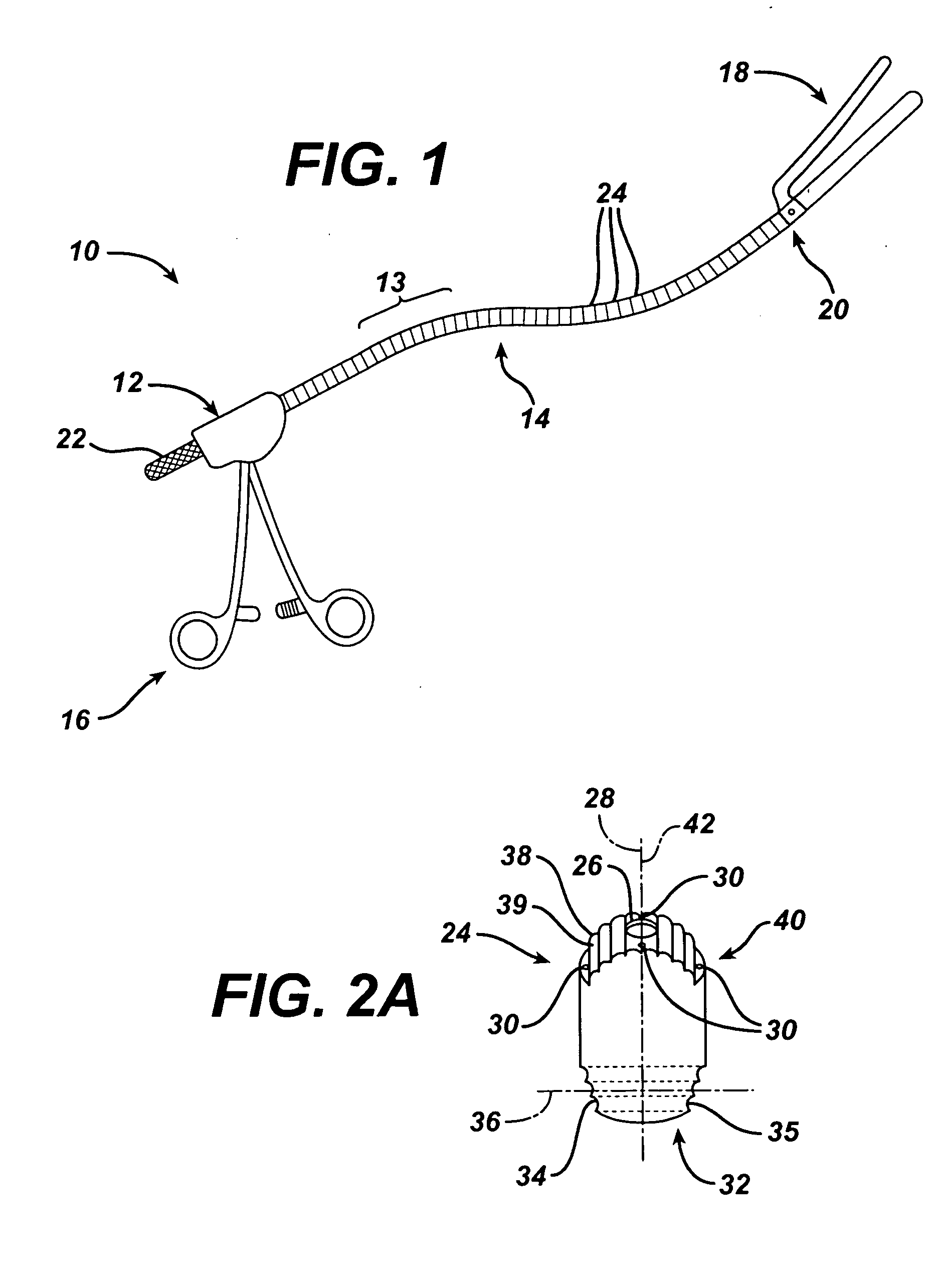
[0022] Referring now to FIG. 1, shown is a surgical instrument, generally 10, according to the present invention. The surgical instrument comprises a proximal base section 12, and a malleable shaft section 14. The base section 12 is adapted for the surgeon to manipulate by hand. It includes actuating levers 16 for actuating a remote apparatus 18 carried on a distal end 20 of the malleable shaft section 14. In this case, the remote apparatus is a clamp. Other remote apparatus contemplated include, but are not limited to, surgical retractors or stabilizers, which may or may not include remote actuation, ligation, ablation, and endoscopy tools. Neither is the present invention limited to only one remote apparatus.

[0023] In alternate embodiments, the proximal base section may be additionally or alternately adapted for securement to additional surgical hardware, including, but not limited to, a surgical retractor or other apparatus. Base section 12 will also include an actuator 22 to tra...

embodiment 200

[0034] Referring now to FIG. 5, another embodiment 200 of the present invention including a malleable shaft section 214 that changes diameter along its length is shown. In this embodiment, the shaft is comprised of a proximal first plurality of first shaft elements 224a, and a distal second plurality of second shaft elements 224b. These first shaft elements 224a and second shaft elements 224b may be generally similar to each other, but for their size. Further, a transitional shaft element 224c is provided at the interface between the first shaft elements 224a and second shaft elements 224b. Transitional shaft element 224c, shown in greater detail in FIG. 6, will have a proximal end 232c which is generally similar to a proximal end of a first shaft element 224a, and a distal end 240c which is generally similar to a distal end of a second shaft element 224b. Distributed axial through holes 230c will adjust position accordingly with the change in size, shape, and / or diameter to effect ...


PUM


Abstract

A flexible malleable shaft is made up of a plurality of prismatic shaft elements adjacent one another. A recess is formed in a proximal end of each shaft element, the recess defined along a transverse axis. A protrusion is formed in a distal end of each shaft element, the protrusion defined along a transverse axis. The transverse axes are oriented to one another such that adjacent like shaft elements are aligned with one another when a protrusion of one shaft element is aligned with a recess in an adjacent shaft element. A tension element secured to a distal end of the malleable shaft is in communication with a proximal end of the malleable shaft via an axial through hole. Additionally, a variable stiffness malleable shaft can accommodate the differential lengths of tension elements when applying force to transition the shaft.

Description

BACKGROUND OF THE INVENTION [0001] 1. Field of Invention [0002] The present invention relates to the field of variable stiffness devices and surgical instrumentation. More specifically, it relates to a variable stiffness shaft having means to stiffen the shaft and means to activate a surgical tool carried at a distal end of the shaft independently from one another. [0003] 2. Description of Related Art [0004] Variable stiffness devices are used in primarily two situations during a surgical procedures. The first involves the accurate positioning of a surgical device, such as a retractor or stabilizer. A flexible shaft overcomes the difficulty of manipulating a rigid shaft. Once the device is in place, the shaft may be made more rigid, in order to allow the position of the device to be accurately held. [0005] A second situation involves the positioning of multiple surgical devices at the surgical site, thereby congesting the working view or area for the surgeon. This problem is particu...

Claims


Application Information

Patent Timeline
Patent Type & Authority Applications(United States)
IPC IPC(8): A61BA61B17/02A61B17/128A61B17/28A61B17/42
CPCA61B17/0218A61B17/1285A61B2017/2905A61B2017/00323A61B17/29
Inventor DOUGLAS, PETERLABOMBARD, DENISWHIPPLE, GARY R.EVANS, STEPHEN
Owner ETHICON INC
Why Eureka
Try Eureka