Composite stent graft

a stent and composite technology, applied in the field of stent grafts, can solve the problems of significant distortion of the side branch vessel, and achieve the effect of reducing the incidence of stenosis or fibrosis

Active Publication Date: 2005-06-16
COOK MEDICAL TECH LLC
View PDF8 Cites 86 Cited by
  • Summary
  • Abstract
  • Description
  • Claims
  • Application Information

AI Technical Summary

Benefits of technology

[0009] It will be seen that by this invention there is provided an arrangement by which the balloon expandable stent portion which is substantially rigid can extend from a main graft across an aneurysed space to the side branch artery or vessel and then within the side branch artery the device has self expanding stents disposed within or outside the tubular graft material which provide a degree of flexibility to reduce the incidence of stenosis or fibrosis.
[0010] Preferably, there is a portion of the balloon expandable stent portion which extends beyond the proximal end of the tubular graft material portion. This extension portion allows for expansion of the balloon expandable stent beyond the diameter of the tubular graft material in that extension portion. This enables the extension portion of the balloon expandable stent to be flared to enable it to be connected into a fenestration in a main graft so that it is securely received in it.

Problems solved by technology

There is a problem with the deployment of a branch stent graft from a main stent graft into a side artery for instance.
If a branch stent graft is made substantially flexible, that is, for instance, manufactured with all self expanding stents, then there is a danger that, where a graft extends from a main graft through an aneurysed space within, for instance an aneurysed aorta and then into a side branch artery, such as a renal artery, as the main graft moves the side branch can kink which can close off the lumen through the branch stent graft.
If, however, an essentially rigid stent graft such as a balloon expandable graft is used then the distal end of the stent graft can cause significant distortion of the side branch vessel and there can be a considerable problem with fibrosis, stenosis or damage to the side branch artery at the distal end of the stent graft.

Method used


Image

  • Composite stent graft
  • Composite stent graft
  • Composite stent graft

Examples


Embodiment Construction

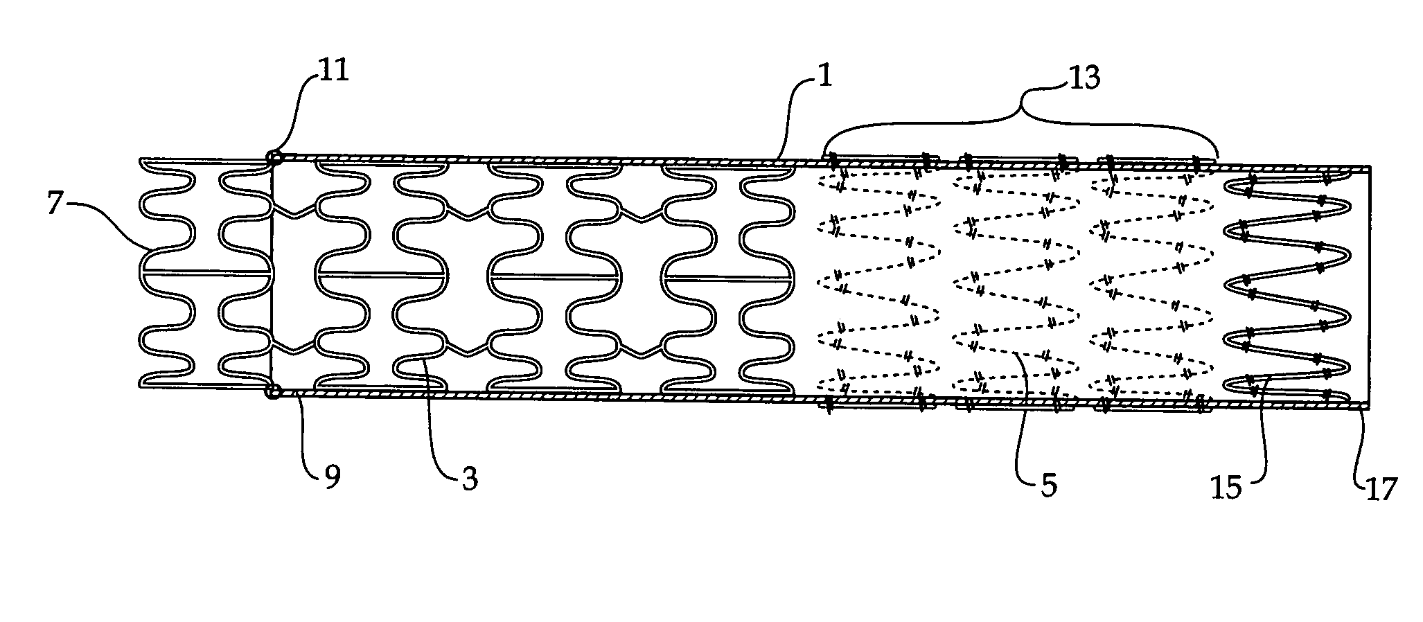
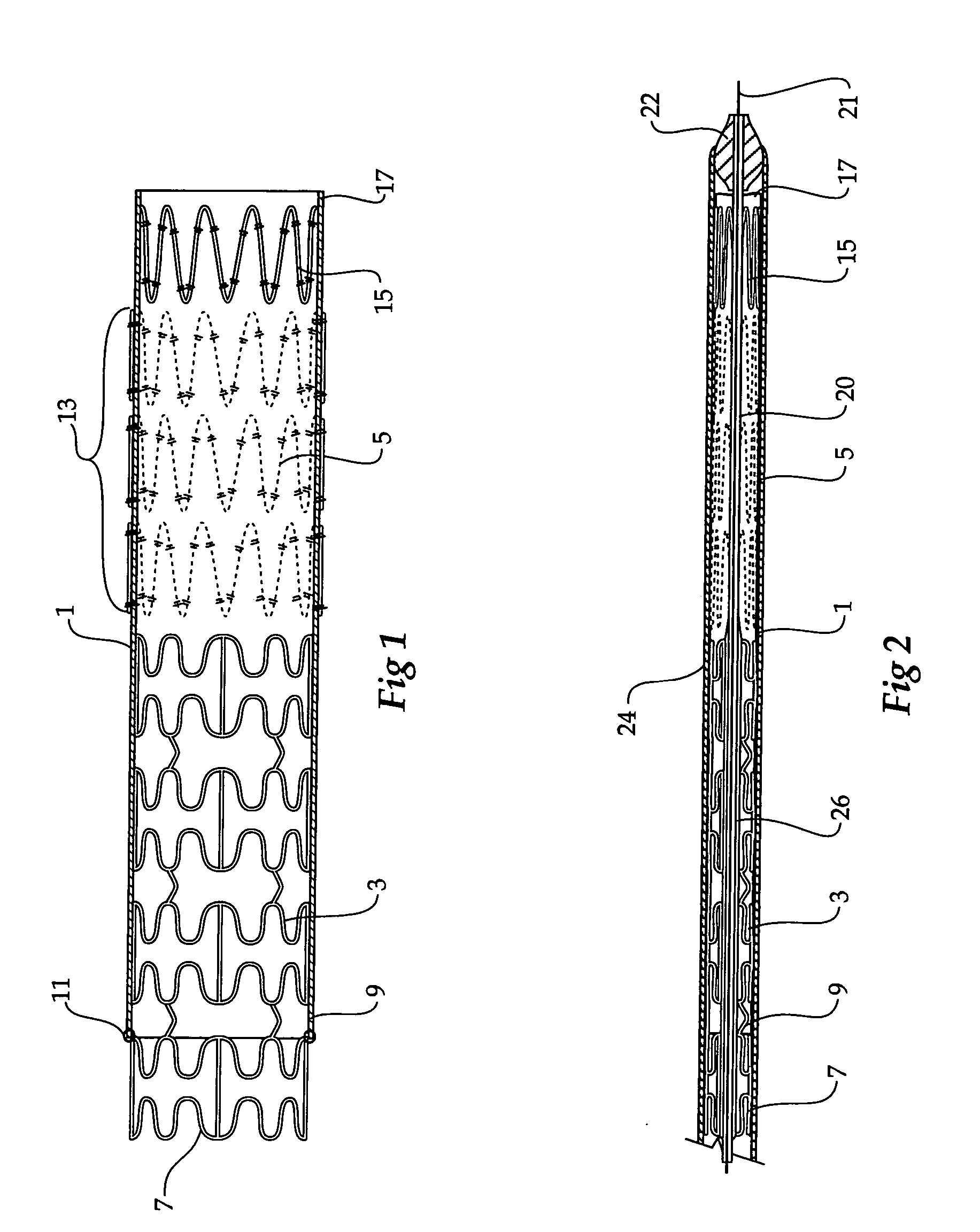
[0044] Now looking more closely at FIGS. 1 and 2, it will be seen that the composite stent graft includes a tubular graft material 1 and within the tubular graft material there is an balloon expandable stent 3 (shown in an expanded configuration in FIG. 1 and in a radially compressed condition in FIG. 2) and a number of self expanding stents 5. The balloon expandable stent 3 has a particular configuration of struts shown but the invention is not limited to any one configuration of struts. The balloon expandable stent 3 has an extension portion 7 which extends beyond the proximal end 9 of the tubular graft material 1. The tubular graft material 1 is stitched at 11 to the balloon expandable stent. Further stitching can also be provided. The self expanding stents 5 are positioned on the outside of the tubular graft material in the region 13 and the final self expanding stent 15 is positioned on the inside of the tubular graft material 1 at the distal end 17 of the tubular graft materia...


PUM


Abstract

A composite stent graft has a balloon expandable stent portion ( 3 ), a tubular graft material portion ( 1 ) inside or outside of the balloon expandable stent portion and self expanding stents ( 5 ) associated with the tubular graft material portion. Part ( 7 ) of the balloon expandable stent portion can extend beyond the proximal end ( 9 ) of the tubular graft material portion. The tubular graft material can be polytetrafluoroethylene, Dacron, Thoralon(TM), polyamide, small intestine submucosa, collagenous extracellular matrix material, or any other suitable biocompatible material. A method of deploying which includes flaring a part ( 7 ) of the balloon expandable stent portion is also discussed.

Description

CROSS-REFERENCE TO RELATED APPLICATIONS [0001] This application claims priority of provisional application Ser. No. 60 / 510,259 filed Oct. 10, 2003.TECHNICAL FIELD [0002] This invention relates to a stent graft for use in the human or animal body and more particularly to a stent graft which can be used as a side branch stent graft from a main vessel stent graft. BACKGROUND OF THE INVENTION [0003] There is a problem with the deployment of a branch stent graft from a main stent graft into a side artery for instance. If a branch stent graft is made substantially flexible, that is, for instance, manufactured with all self expanding stents, then there is a danger that, where a graft extends from a main graft through an aneurysed space within, for instance an aneurysed aorta and then into a side branch artery, such as a renal artery, as the main graft moves the side branch can kink which can close off the lumen through the branch stent graft. [0004] If, however, an essentially rigid stent ...

Claims


Application Information

Patent Timeline
Patent Type & Authority Applications(United States)
IPC IPC(8): A61F2/00A61F2/06A61F2/82
CPCA61F2/07A61F2/91A61F2/954A61F2/958A61F2002/061A61F2/852A61F2002/821A61F2250/0039A61F2/89A61F2/915A61F2002/075
Inventor HARTLEY, DAVID ERNEST
Owner COOK MEDICAL TECH LLC
Why Eureka
Try Eureka