Broadband full white reflective display structure

a reflective display and wideband technology, applied in the direction of identification means, instruments, planar/plate-like light guides, etc., can solve the problems of colour shift in the function of viewing angle of reflective colour displays, and achieve the effect of improving image quality

Inactive Publication Date: 2005-06-23
BARCO NV
View PDF8 Cites 113 Cited by
  • Summary
  • Abstract
  • Description
  • Claims
  • Application Information

AI Technical Summary

Benefits of technology

[0003] It is an object of the present invention to provide a reflective full colour display that has an improved image quality as well as a method of operating and manufacturing the same.

Problems solved by technology

Reflective colour displays, such as e.g. LCD displays, are known to suffer from colour shift in function of the viewing angle.

Method used


Image

  • Broadband full white reflective display structure
  • Broadband full white reflective display structure
  • Broadband full white reflective display structure

Examples


Embodiment Construction

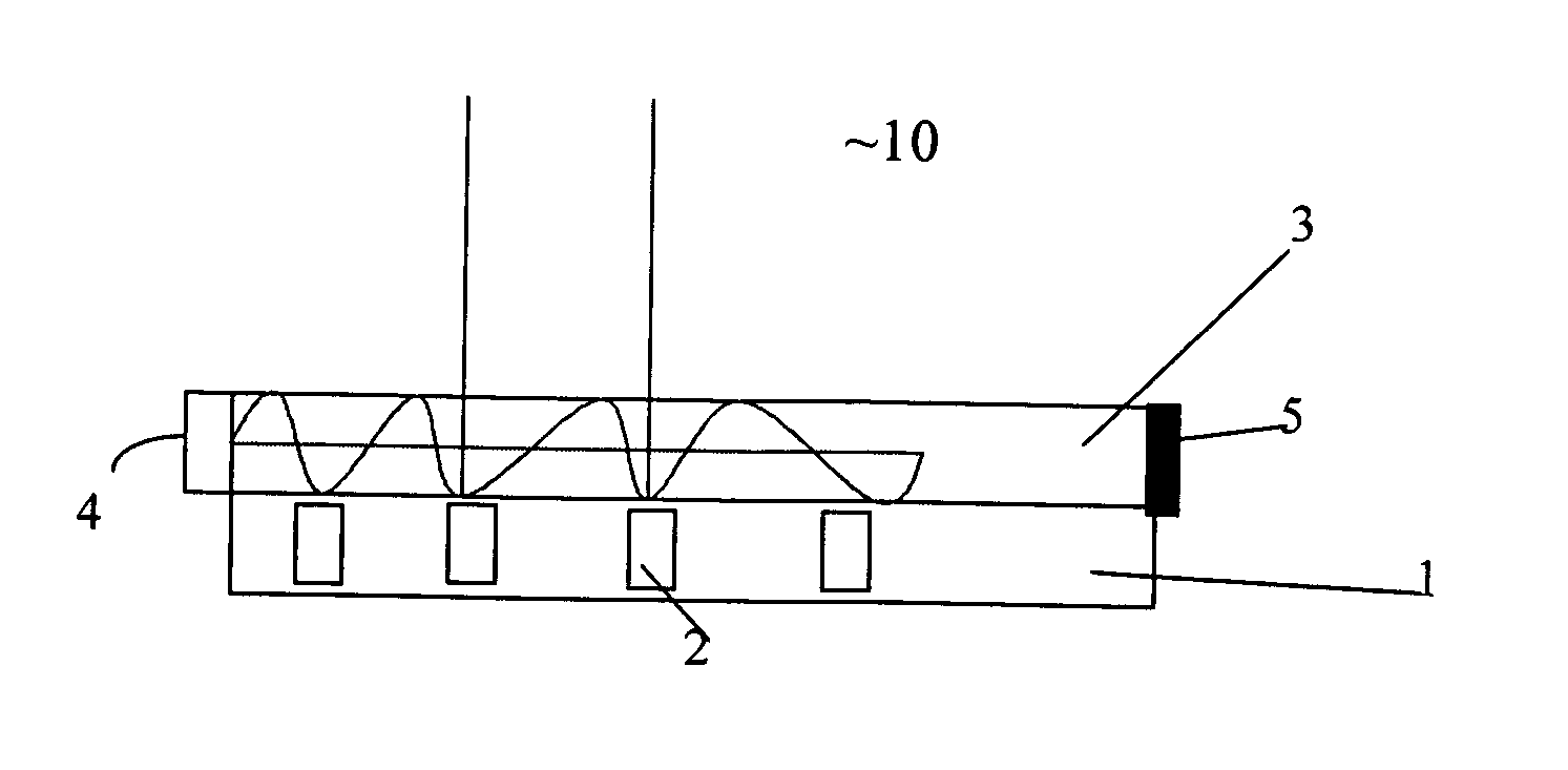
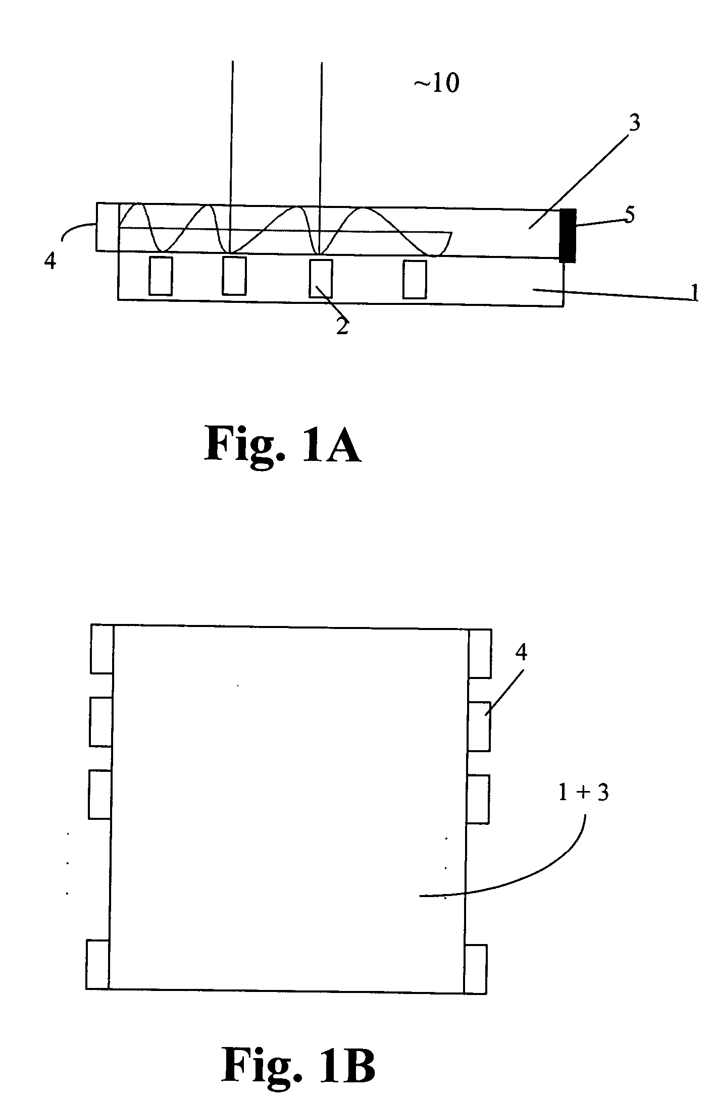
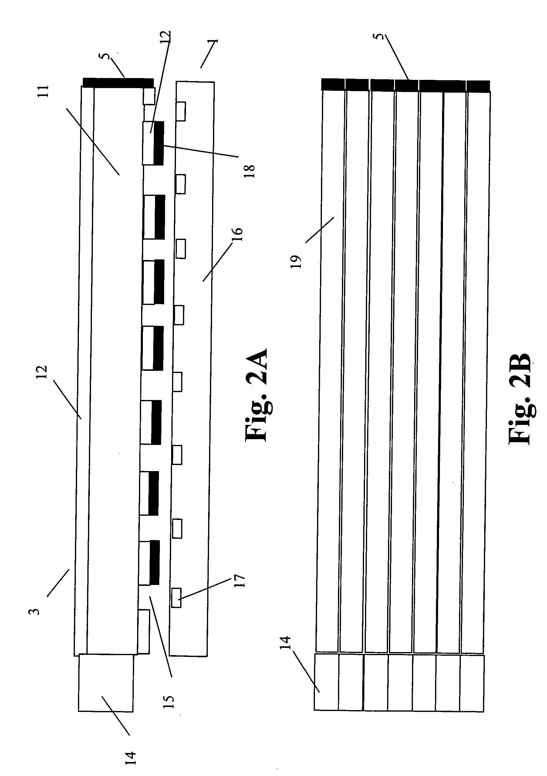
[0029] The present invention will be described with respect to particular embodiments and with reference to certain drawings but the invention is not limited thereto but only by the claims. The drawings described are only schematic and are non-limiting. In the drawings, the size of some of the elements may be exaggerated and not drawn on scale for illustrative purposes.

[0030] Furthermore, the terms first, second, third and the like in the description and in the claims, are used for distinguishing between similar elements and not necessarily for describing a sequential or chronological order. It is to be understood that the terms so used are interchangeable under appropriate circumstances and that the embodiments of the invention described herein are capable of operation in other sequences than described or illustrated herein.

[0031] Moreover, the terms top, bottom, over, under and the like in the description and the claims are used for descriptive purposes and not necessarily for d...


PUM

PropertyMeasurementUnit
angleaaaaaaaaaa
angleaaaaaaaaaa
areaaaaaaaaaaa

Abstract

The present invention provides a fixed format display panel having a front side and a rear side and comprising a plurality of rows of addressable pixelated reflective light modulating means and at least one longitudinal light guiding structure having at least one emissive light source at at least one of a first and second end. Light coming from the at least one emissive light source is projected across the display panel through the at least one longitudinal light guiding structure and is reflected by said light modulating means through an angle towards the front side.

Description

TECHNICAL FIELD OF THE INVENTION [0001] The present invention relates to a reflective colour display with improved image quality and methods of driving and manufacturing the same. BACKGROUND OF THE INVENTION [0002] Reflective colour displays, such as e.g. LCD displays, are known to suffer from colour shift in function of the viewing angle. SUMMARY OF THE INVENTION [0003] It is an object of the present invention to provide a reflective full colour display that has an improved image quality as well as a method of operating and manufacturing the same. [0004] The above objective is accomplished by a method and device according to the present invention. [0005] The present invention provides a fixed format display panel, e.g. a flat panel display. Fixed format display panels comprise a matrix or array of “cells” or “pixels” each producing or controlling light over a small area. The display panel according to the present invention may be described as follows: a display panel having a front...

Claims


Application Information

Patent Timeline
Patent Type & Authority Applications(United States)
IPC IPC(8): C09K19/34F21V8/00G02B26/02G09F9/37G09F13/02
CPCG02B6/0011G02B6/0055G02B6/0056G09F13/02G02F2001/133616G02F2001/133622G09F9/372G02B26/02G02F1/133616G02F1/133622
Inventor THIELEMANS, ROBBIE
Owner BARCO NV
Why Eureka
Try Eureka