Enhanced cost effective method for high current measurements

a high current and cost-effective technology, applied in the field of alternating current measurement, can solve the problems of limited vehicle range, inconvenient use, and insufficient technology for storing large amounts of electrical energy, and achieve the effect of preventing current flow through the bol

Inactive Publication Date: 2005-06-23
BAE SYSTEMS CONTROLS INC
View PDF5 Cites 33 Cited by
  • Summary
  • Abstract
  • Description
  • Claims
  • Application Information

AI Technical Summary

Benefits of technology

This patent describes an improved design that prevents electricity from flowing through certain parts of an electronic device. It does this by adding extra material called an insulating arrangement between two components. This can help reduce the risk of damage caused by electrostatic discharge (ESD) events.

Problems solved by technology

The technical problem addressed in this patent relates to improving the accuracy of measuring small amounts of electric current in a printed circuit assembly. The solution involves placing a current sensor next to a specific conductor within the assembly, but it needs to have a smaller size compared to the main current carrying conductor(s). To address this issue, the patent describes various methods for creating gaps in the design of the printed circuit board to allow for controlled current distribution and increased cooling efficiency.

Method used


Image

  • Enhanced cost effective method for high current measurements
  • Enhanced cost effective method for high current measurements
  • Enhanced cost effective method for high current measurements

Examples


Embodiment Construction

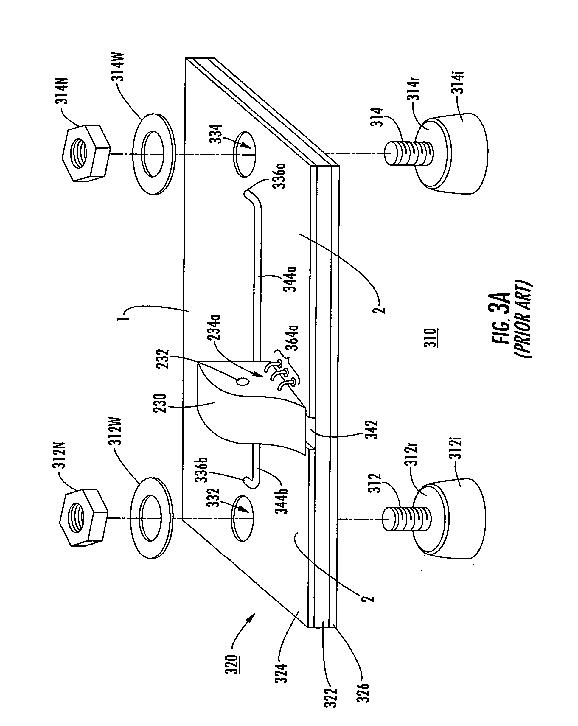
[0043] It will be noticed that the arrangement of FIG. 3a makes the current connections between the sensor and the external connections by way of a threaded stud and corresponding nuts. Equivalently, bolts could be used. In any case, electrical connections often require threaded connector devices. According to an aspect of the invention, a low-cost current sensor arrangement makes use of the bolted (or stud-and-nut) connection to simplify the current sensor arrangement.

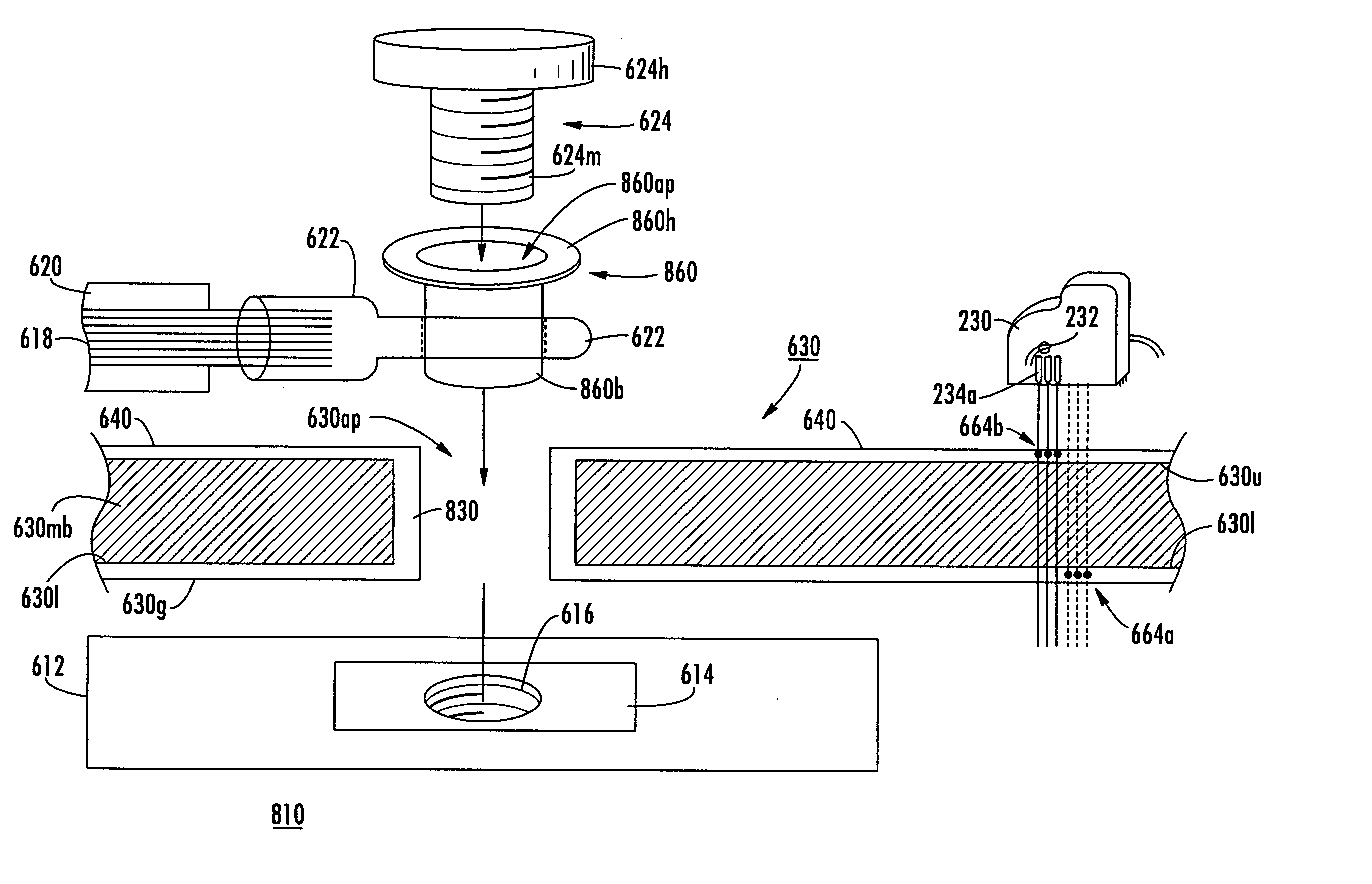
[0044]FIG. 6a illustrates in simplified god's-eye view a structure 610 according to an aspect of the invention. In FIG. 6a, a solid-state power handling device, such as a gate-controlled bipolar switch, is illustrated as a block 612. A power terminal of the power device 612, such as an emitter or collector in the case of a gate-controlled bipolar device, is illustrated as an electrically conductive layer 614. A threaded aperture 16 is defined in the switch 612, to provide for tight contact of a current-carrying condu...


PUM


Abstract

An electrical connection between a power source and a threaded aperture in a power device is made by means of a terminal lug and a bolt. In order to measure the current, a second electrical path is made in parallel with the bolted connection, and current in the second path is sensed. The bolt may carry the main current, or an insulating spacer may be used which prevents significant current flow in the bolt. In one embodiment, the parallel current path extends through a conductor arrangement including additional lugs through which the bolt passes, and in another arrangement the parallel path extends through traces of a printed circuit board.

Description


Claims


Application Information

Patent Timeline
Owner BAE SYSTEMS CONTROLS INC
Why Eureka
Try Eureka