Chua's circuit and it's use in hyperchaotic circuit

Inactive Publication Date: 2005-06-23
STMICROELECTRONICS PVT LTD
View PDF7 Cites 21 Cited by
  • Summary
  • Abstract
  • Description
  • Claims
  • Application Information

AI Technical Summary

Benefits of technology

[0043] An improved Chua's circuit providing current mode operation, access to all state variables, minimum use of grounded passive elements, and freedom from passive component matching comprising;

Problems solved by technology

However, use of any of these circuits will not only add the disadvantage of those proposal of Chua's circuit but also one voltage buffer and one floating resistor per coupling is required which in turn make the final circuit bulky and inefficient in terms of power consumption.

Method used


Image

  • Chua's circuit and it's use in hyperchaotic circuit
  • Chua's circuit and it's use in hyperchaotic circuit
  • Chua's circuit and it's use in hyperchaotic circuit

Examples


Embodiment Construction

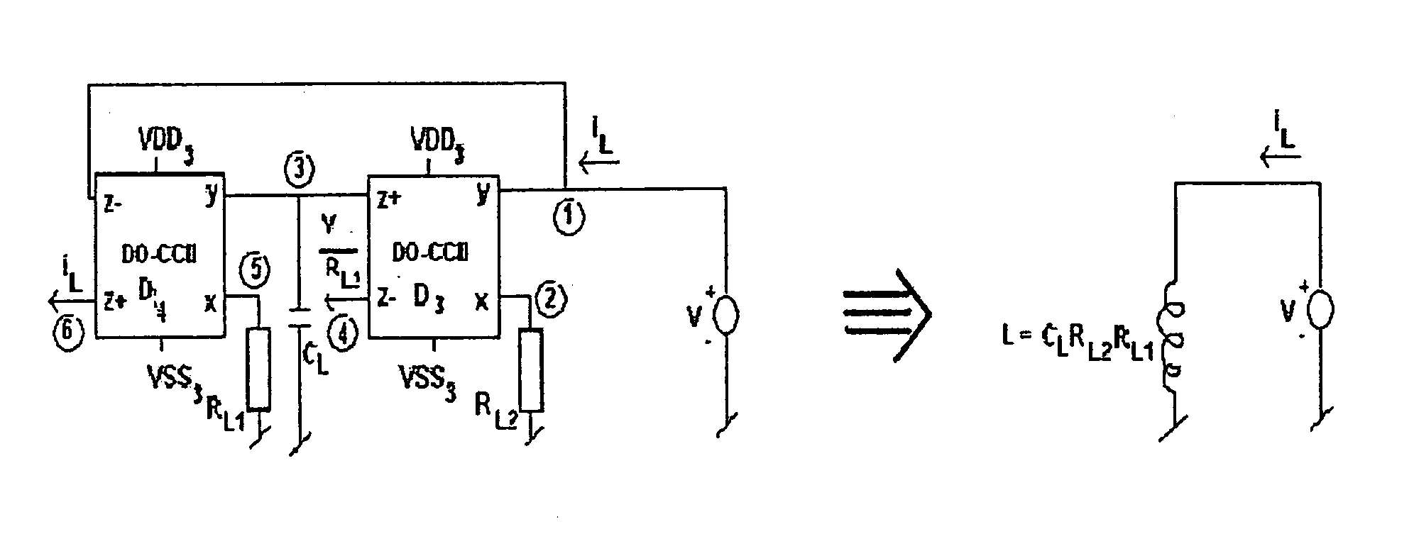
[0076] The present invention provides a Chua's circuit using Dual Output (second-generation) Current Conveyer (DO-CC II) as one embodiment. It also provides Chua's circuit implementation using Multiple Output Current Conveyor and further it provides the design of a hyperchaotic circuit using Multiple Output Current Conveyor based Chua's circuit as other embodiments.

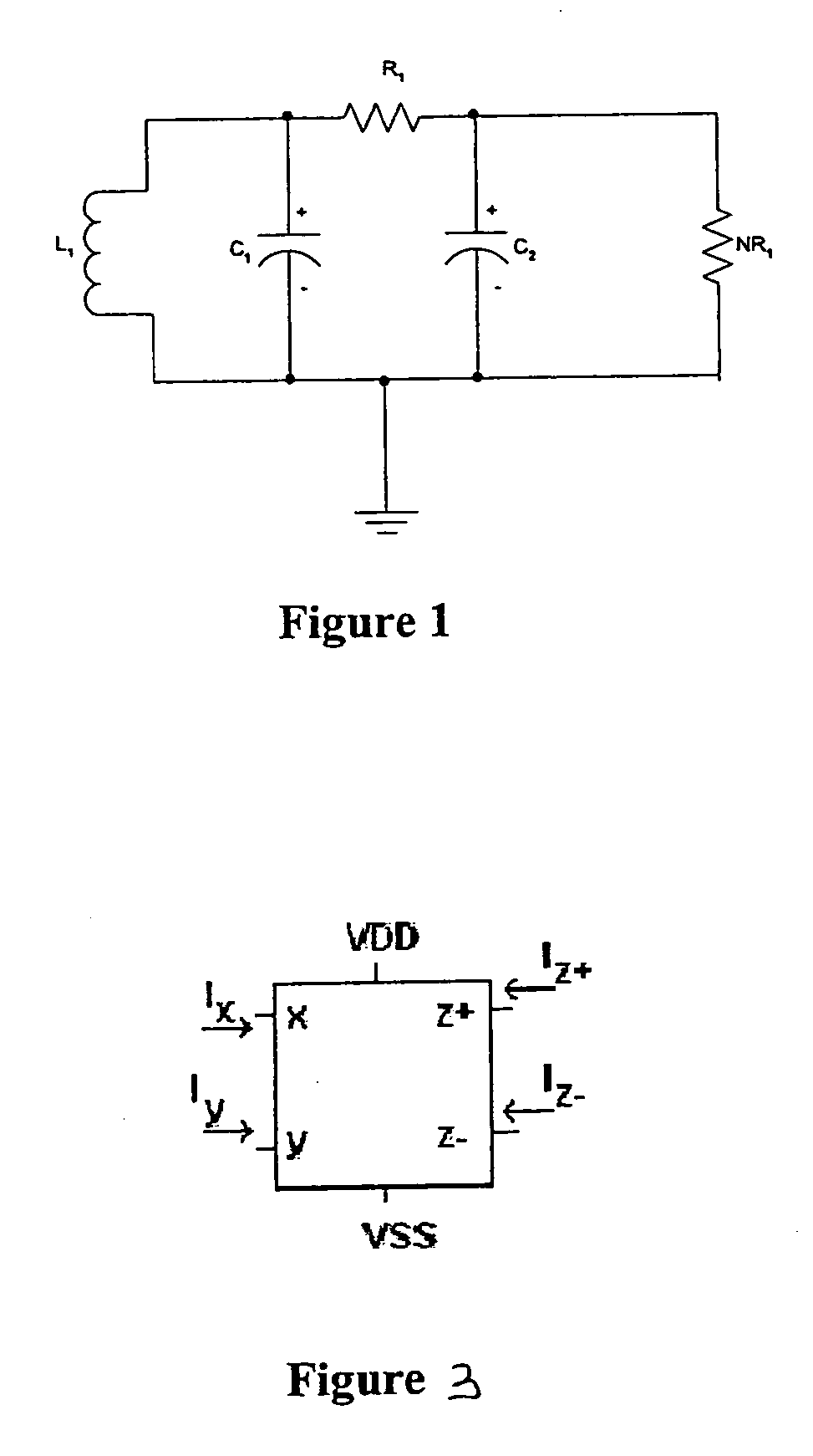
[0077]FIG. 1 has already been discussed under the section “background of the invention”.

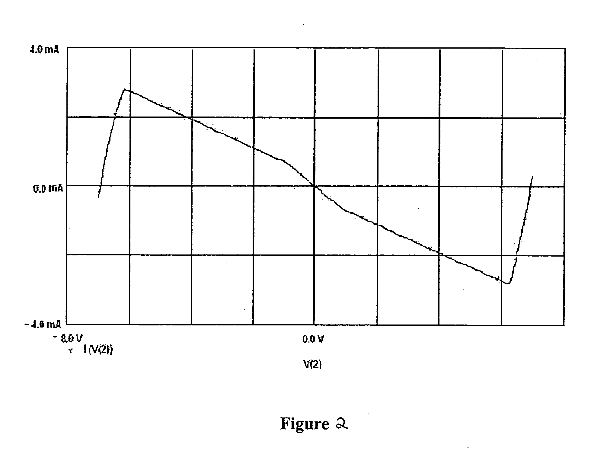
[0078]FIG. 2 has also been discussed under the section “background of the invention”

[0079]FIG. 3 shows the coupling of ‘n’ Chua's circuit to achieve synchronization. The system thus formed is used to solve the following set of equations C1⁢ⅆvC1(1)ⅆt=G⁡(vC2(1)-vC1(1))-f⁡(vC1(1))C2⁢ⅆvC2(1)ⅆt=G⁡(vC1(1)-vC2(1))+iL(1)+f⁡(vC1(1))+1RK⁢(vC2(2)-vC2(1))L⁢ⅆvL(1)ⅆt=-vC2(1)C1⁢ⅆvC1(2)ⅆt=G⁡(vC2(2)-vC1(2))-f⁡(vC1(2))C2⁢ⅆvC2(2)ⅆt=G⁡(vC1(2)-vC2(2))+iL(2)+f⁡(vC1(2))+1RK⁢(vC2(3)-vC2(2))L⁢ⅆvL(2)ⅆt=-vC2(2)⋮C1⁢ⅆvC1(n)ⅆt=G⁡(vC2(n)-vC1(n))-f⁡(vC1(n))C2⁢ⅆvC2...


PUM


Abstract

The present invention provides an improved Chua's circuit providing current mode operation, access to all state variables, minimum use of grounded passive elements, and freedom from passive component matching comprising a dual output current conveyer based inductor having one grounded terminal, a capacitor connected across the second terminal of said inductor, a resistor having one terminal connected to the second terminal of said inductor, the second terminal of said resistor connected to one terminal of a second capacitor the other end of which is grounded, and a pair of dual output current conveyers connected together to form a 2-terminal negative resistance having one terminal connected to ground and the second terminal connected to the second terminal of said resistance.

Description

FIELD OF THE INVENTION [0001] The invention relates to an improved Chua's circuit more particularly, the invention relates to a Chua's circuit using a Dual Output Current Conveyer (DO-CC II). The invention also implements Chua's circuit using Multiple Output Current Conveyor (MO-CCII) and uses the said designed circuit to generate a hyperchaotic circuit. BACKGROUND OF THE INVENTION [0002]FIG. 1 shows a generalized Chua's circuit that has a parallel combination of a capacitor, C2, a Chua's diode, connected to an L-C tank circuit that consists of a second capacitor C1 connected in parallel with a serially connected inductor, L1. In addition, a first voltage, V1 is defined across capacitor C1 and second voltage, V2 defined across capacitor C2 with the positive orientation of voltages V1 and V2 both being at the positive end of the corresponding capacitor. Finally, there is a linear resistor R1 connected between the positive terminals of each capacitor. [0003] In a typical configuration...

Claims


Application Information

Patent Timeline
IPC IPC(8): H03F1/34H03H11/00H03H11/52
CPCH03F1/34
Inventor GANDHI, GAURAV
Owner STMICROELECTRONICS PVT LTD
Why Eureka
Try Eureka