Cube corner retroreflector with limited range

a retroreflector and cube corner technology, applied in the field of retroreflectors, can solve the problems of limited intensity of reflected light, avoid excessive road preview, selectively limit the range at which the article is located, and avoid distraction of the driver

Active Publication Date: 2005-06-30
AVERY DENNISON CORP
View PDF20 Cites 21 Cited by
  • Summary
  • Abstract
  • Description
  • Claims
  • Application Information

AI Technical Summary

Benefits of technology

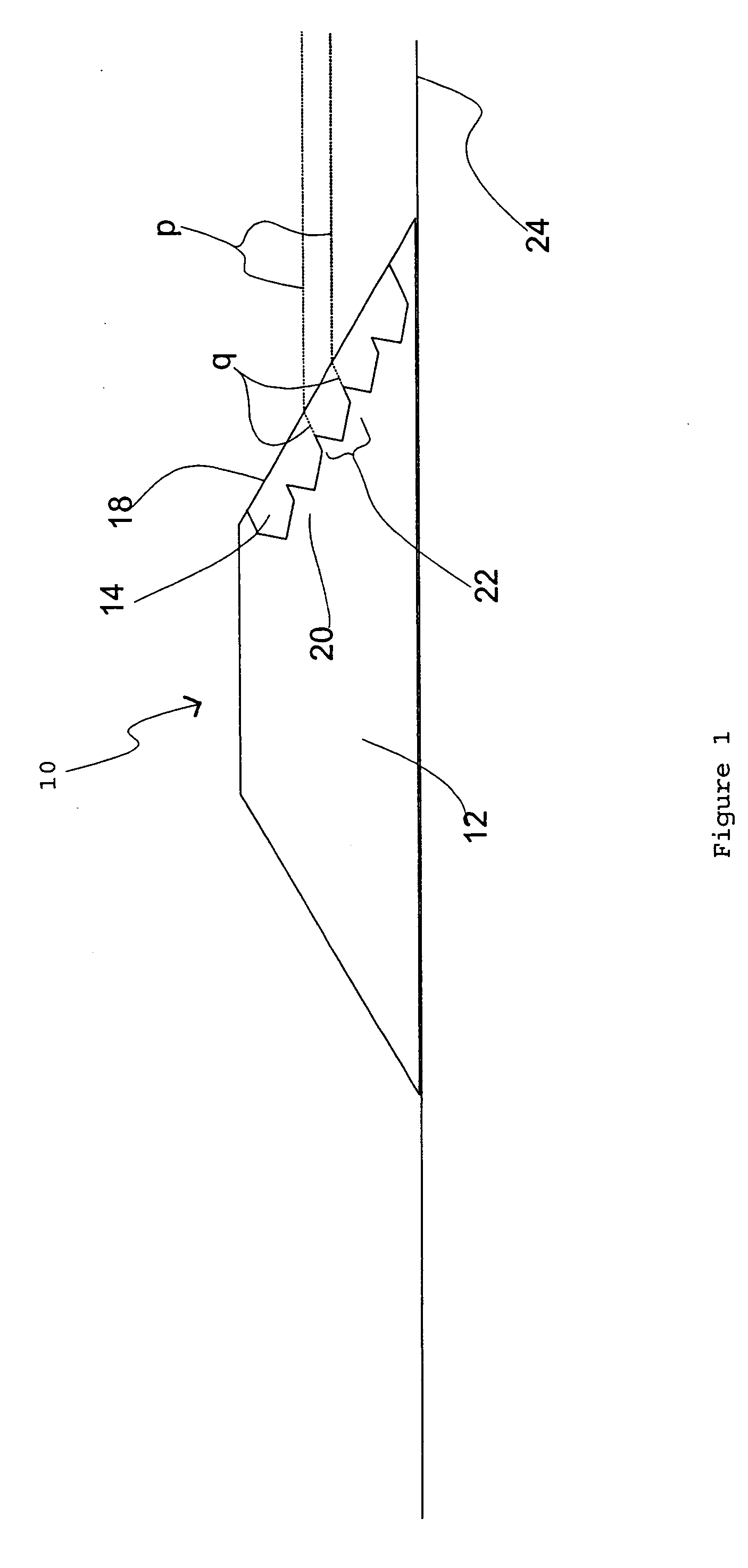
[0008] The present invention provides a retroreflective article having cube corner prism elements that are constructed to selectively limit the range at which the article is visible. The retroreflection of light from the article at small observation angles, for example 0.3 degrees and less, is selectively limited. While the article may still be visible at long distance, the intensity of the reflected light is limited. This has application, for example, in raised pavement markers, so that the marker is visible to a vehicle driver sufficiently in advance of the marker to enable the driver to react to the marker, but with limited visibility at larger distances from the marker to avoid excessive road preview and avoid distraction of the driver.
[0009] Retroreflective road markers made in accordance with the present invention will have limited visibility beyond a certain distance D, and high visibility at substantially closer distances. A consequence is that the retroreflectance of such articles is not a simply decreasing function of observation angle, as is the retroreflectance of conventional retroreflectors. The retroreflectance of an article made in accordance with the present invention generally has a peak value at a selected observation angle with decline at observation angles less than the selected observation angle to assure more rapid decrease of visibility beyond a selected distance than conventional retroreflectors exhibit.

Problems solved by technology

While the article may still be visible at long distance, the intensity of the reflected light is limited.
This has application, for example, in raised pavement markers, so that the marker is visible to a vehicle driver sufficiently in advance of the marker to enable the driver to react to the marker, but with limited visibility at larger distances from the marker to avoid excessive road preview and avoid distraction of the driver.

Method used


Image

  • Cube corner retroreflector with limited range
  • Cube corner retroreflector with limited range
  • Cube corner retroreflector with limited range

Examples


example 1

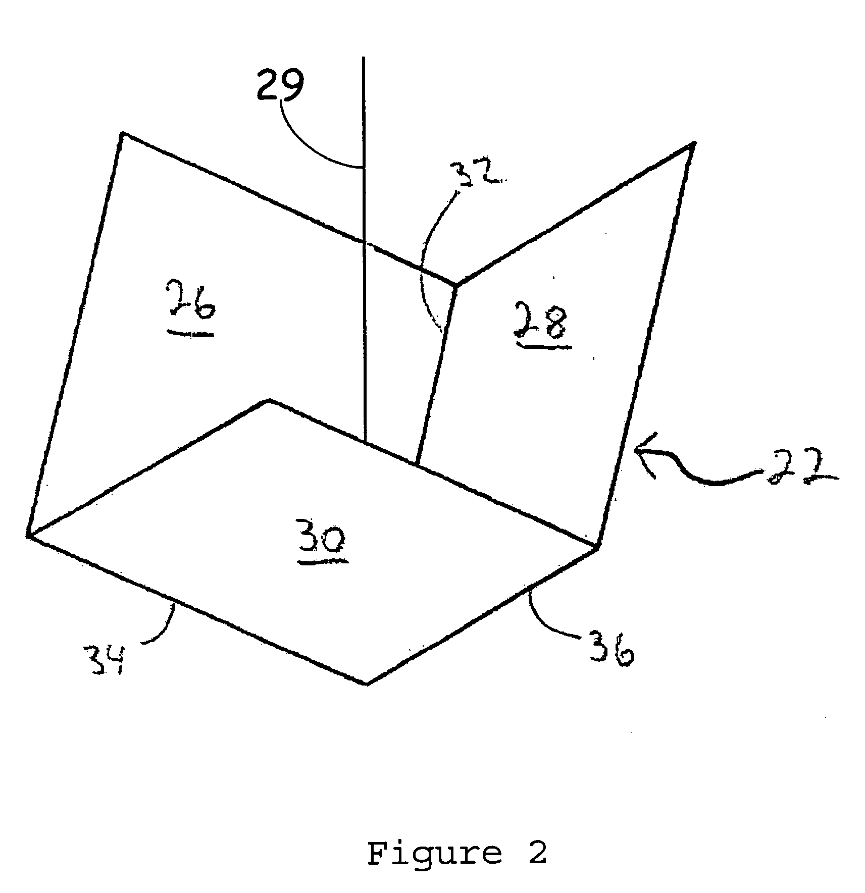
[0121] A retroreflective article in accordance with the present invention can be made with cube corner elements 22, oriented as in FIGS. 4A or 4B, that direct the retroreflected intensity away from observation angles between 0 and 0.2 degrees. In this case, 0.2 degrees is the observation angle selected to represent “too far”; 0.4 degrees is selected to represent “far enough”; 1.0 degree is selected to represent “close enough”. A tool having dihedral angle errors of about +0.04 degrees, about −0.09 degrees, and about +0.07 degrees can be used to mold acrylic resin in a process that transforms dihedral angle errors by about −0.04 degrees, about −0.04 degrees, and about −0.07 degrees, respectively, to produce cube corner elements 22 having idealized dihedral angle errors of about 0 degrees, about −0.13 degrees, and about 0 degrees. The tool used to produce this cube corner element has the retroreflected spot pattern of FIG. 9A. The molded cube corner element in a raised pavement marker...

example 2

[0129] This example will satisfy the driver-on-left criterion instead of the international criterion. The molded cubes of Example 1 having dihedral angle errors {0,−0.13, 0} are called A-cubes. Molded cubes having dihedral angle errors {−0.13, 0, +0.13} are called B-cubes. Molded cubes having dihedral angle errors {+0.13, 0, +0.13} are called C-cubes. FIG. 9C shows the spot patterns from the A-cubes. FIG. 15A shows the spot pattern from the B-cubes. FIG. 15B shows the spot pattern from the C-cubes. The B-cube puts two spots where the C-cube corner puts one, and vice versa. The B-cube pattern and C-cube pattern partly coincide with the pattern from the A-cubes.

[0130] If the molding transformation is {−0.04, −0.04, −0.07} then in the tool, A-cubes have dihedral angle errors {+0.04, −0.09, +0.07}, B-cubes have dihedral angle errors {0.09, +0.04, +0.20} and C-cubes have dihedral angle errors {+0.17, +0.04, +0.20}.

[0131] Either A-cubes , B-cubes, or C-cubes will satisfy the driver-on-l...

example 3

[0135] This example has an extended retroreflection pattern, by means of mixing two spot patterns of different scales. FIG. 10 shows the addition of the spot pattern, shown with solid dots, corresponding to dihedral errors {−0.02°, 0.12°, 0.04°} to the spot pattern, shown with hollow dots, corresponding to dihedral errors {−0.03°, 0.18°, 0.06°}. The second pattern is exactly 1.5× the size of the first. Note that the cubes in the tool used to make these two patterns will not themselves exhibit patterns differing in scale. For example, if the molding transformation is {−0.04°, −0.04°, −0.07°}, then the cubes in the tools will be {0.02°, 0.16°, 0.11°} and {0.01°, 0.22°, 0.13°} which are not proportionate.

[0136] Combination of patterns of different size accommodates the variation with road distance of the positions of the of the observer relative to the headlights as shown in FIG. 11. A lens comprised of macrocubes will have between about 100 and about 300 cube corners, allowing much f...


PUM

PropertyMeasurementUnit
observation angleaaaaaaaaaa
distancesaaaaaaaaaa

Abstract

Retroreflective articles having cube corner elements are disclosed, with the dihedral angle errors of the cube corner elements selected to limit the visibility range of the retroreflective article. Also disclosed are methods for making the cube corner elements and the retroreflective articles.

Description

CROSS REFERENCE TO RELATED APPLICATION [0001] This application claims the benefit under 35 U.S.C. § 11 9(e) of U.S. Provisional Application 60 / 532,496 filed Dec. 24, 2003, titled CUBE CORNER RETROREFLECTOR WITH LIMITED RANGE, which application is hereby incorporated by reference in its entirety.BACKGROUND [0002] The present invention generally relates to retroreflective articles, and, more specifically, to cube corner retroreflectors having selectively reduced visibility range. [0003] Retroreflective articles are well-known for applications such as highway signs, safety reflectors, and road markers. Generally, cube corner versions of these articles have a frontal lens of clear, colored or uncolored resin, such as methyl methacrylate, with a smooth front surface and a plurality of retroreflective cube corner elements on the rear surface. The cube corner elements each have three reflecting faces. [0004] Light from a remote source passes through the smooth front surface, reflects off e...

Claims


Application Information

Patent Timeline
Patent Type & Authority Applications(United States)
IPC IPC(8): B29D11/00E01F9/06G02B5/122
CPCG02B5/122Y10S425/808
Inventor COUZIN, DENNIS I.
Owner AVERY DENNISON CORP
Why Eureka
Try Eureka