Optical connector, optical fiber with connector, optical fiber connecting device, and optical fiber connection method

a technology of optical fibers and connectors, applied in the direction of optics, optical light guides, instruments, etc., can solve the problems of affecting the connection, affecting the connection, and affecting the connection, so as to achieve the effect of suppressing as much as possible the loss of connection

Inactive Publication Date: 2005-06-30
3M INNOVATIVE PROPERTIES CO
View PDF30 Cites 138 Cited by
  • Summary
  • Abstract
  • Description
  • Claims
  • Application Information

AI Technical Summary

Benefits of technology

[0046] According to further invention aspects set forth above, even when performing connector attachment work on a construction site, it is possible to suppress as much as possible the conne...

Problems solved by technology

With a conventional socket-type optical connector with a built-in aligning sleeve member, in particular due to the external dimensions in the ferrule extension direction, sometimes it is difficult to hold the connector with a margin of space in the switchbox to an extent able to avoid undesirable bending of the optical fiber cable.
On the other hand, a plug-type optical connector can be attached to an optical fiber cord in advance at the factory before shipment, but is more susceptible to contact by the hand or deposition of dirt than a socket-type optical...

Method used


Image

  • Optical connector, optical fiber with connector, optical fiber connecting device, and optical fiber connection method
  • Optical connector, optical fiber with connector, optical fiber connecting device, and optical fiber connection method
  • Optical connector, optical fiber with connector, optical fiber connecting device, and optical fiber connection method

Examples


Embodiment Construction

[0071] Below, embodiments of the present invention will be explained in detail with reference to the attached drawings. Throughout the drawings, corresponding components are assigned common reference numerals.

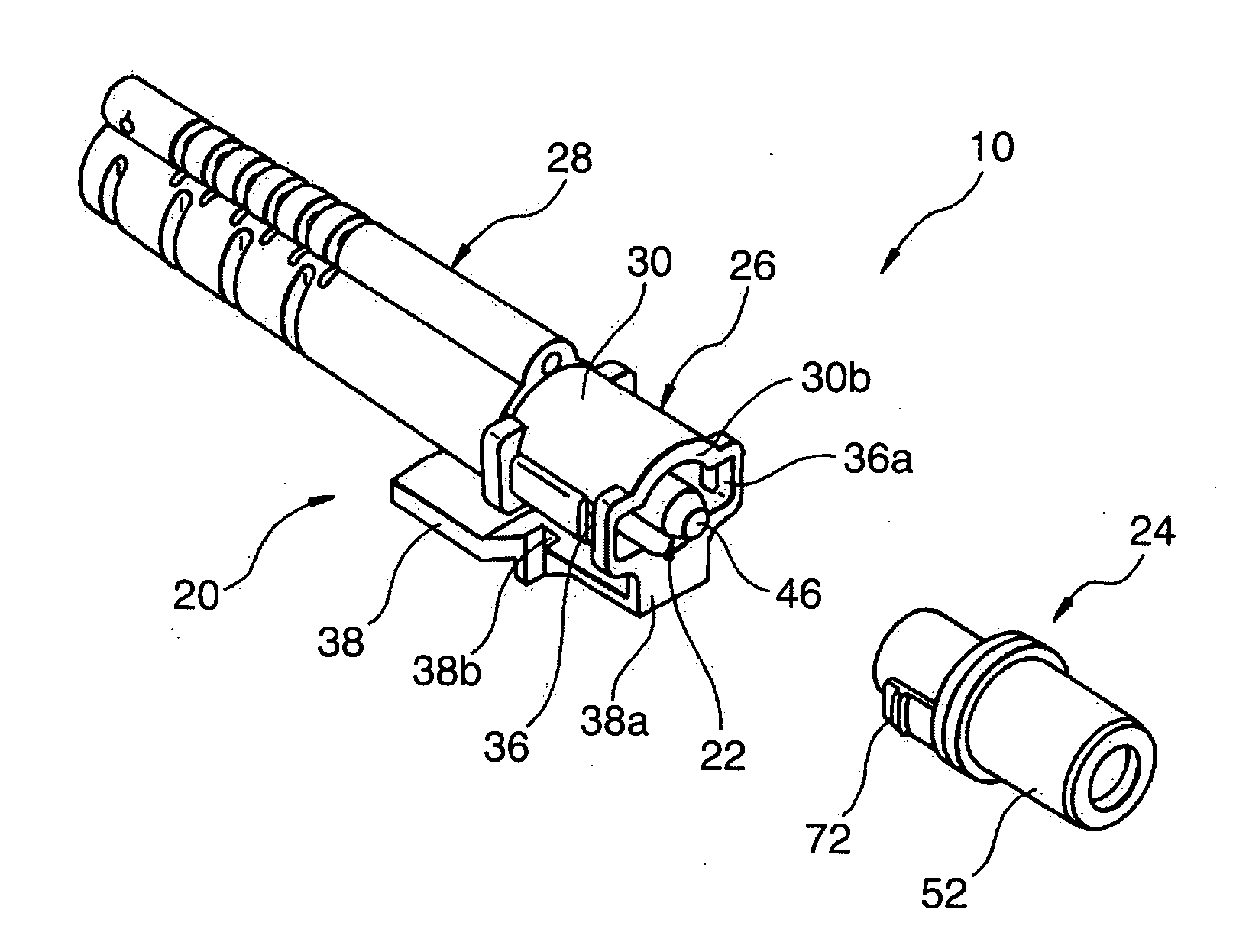
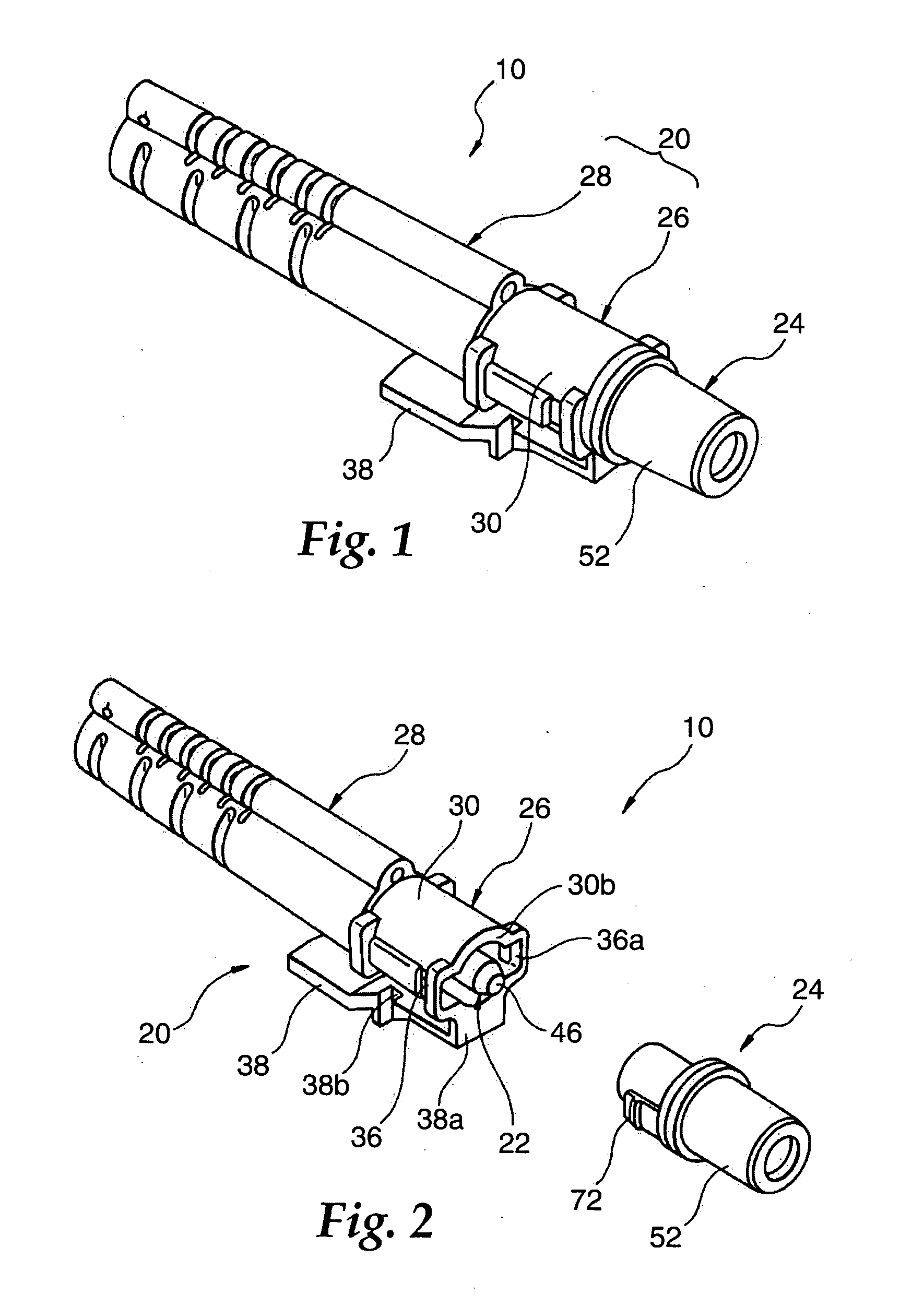
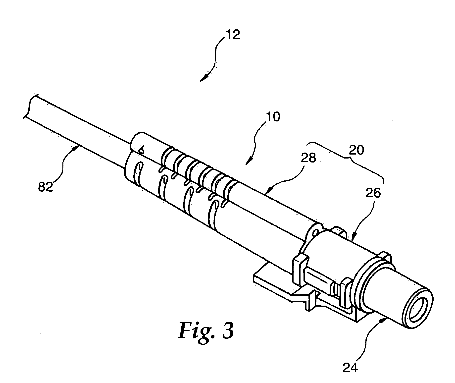
[0072]FIG. 1 and FIG. 2 are views showing a plug-type optical connector 10 according to an embodiment of the present invention, FIG. 3 and FIG. 4 are views showing an optical fiber 12 according to an embodiment of the present invention provided with an optical connector, FIG. 5 and FIG. 6 are views of a socket-type optical connector 14 according to another embodiment of the present invention, FIG. 7 and FIG. 8 are views showing an optical fiber 16 according to another embodiment of the present invention provided with an optical connector 14, and FIG. 9 and FIG. 10 are views of an optical fiber connecting device 18 according to an embodiment of the present invention provided with a plug-type optical connector 10 and a socket-type optical connector 14. The optical connector 10 a...


PUM


Abstract

A plug-type optical connector 10 is provided with a ferrule 22 and an aligning sleeve member 24. The aligning sleeve member 24 receives a portion of the ferrule 22 including an abutting end face 48 inside a bore 58 to prevent staining and damage and uses a movable shutter 54 to prevent light emitted through the ferrule 22 from leaking to the outside. The socket type optical connector 14 is provided with a ferrule 92 and a holding section 94. The optical connector 14 is not provided with an aligning sleeve member and further can hold a coated optical fiber by a holding section 94 behind the ferrule 92 by a radius of curvature of at least a prescribed minimum radius of curvature. Optical loss in the coated optical fiber can be reduced while effectively reducing the external dimensions in the direction of extension of the ferrule 92 at the time of use. An optical fiber connecting device that includes a combination of a pair of optical connectors is also provided to be suitably applied to an optical transmission line laid indoors.

Description

RELATED APPLICATION [0001] This application claims priority from Japanese Application No. 2003-428071, filed Dec. 24, 2003. TECHNICAL FIELD [0002] The present invention relates to technology for connection of optical fibers. More particularly, the present invention relates to an optical connector having a ferrule, an optical fiber having an optical connector attached to an end, an optical fiber connecting device comprising a combination of a pair of optical connectors, and an optical fiber connection method for interconnecting a pair of optical fibers in a state with end faces abutting against each other. BACKGROUND OF THE INVENTION [0003] In technology for connection of optical fibers, there is known an optical connector equipped with a ferrule securing supporting an optical fiber from which the coating has been removed at a predetermined position of the connector body. A single-fiber ferrule generally is a cylindrical member formed with a through hole for holding the fiber along i...

Claims


Application Information

Patent Timeline
IPC IPC(8): G02B6/36G02B6/38
CPCG02B6/3821G02B6/3822G02B6/3825G02B6/3887G02B6/3855G02B6/3874G02B6/3877G02B6/3849G02B6/38875G02B6/38G02B6/36
Inventor YAZAKI, AKIHIKOYAMAUCHI, TAKAYABYLANDER, JAMES R.MORGAN, ERIC M.RAIDER, WESLEY A.TAYLOR, KIRK L.
Owner 3M INNOVATIVE PROPERTIES CO
Why Eureka
Try Eureka