Friction drive device

Inactive Publication Date: 2005-06-30
NISSAN MOTOR CO LTD
View PDF6 Cites 36 Cited by
  • Summary
  • Abstract
  • Description
  • Claims
  • Application Information

AI Technical Summary

Problems solved by technology

The above known conventional friction drive devices, however, encounter a problem that lifetime of the roller and bearings of the rollers are shortened and power transmission efficiency between the rollers deteriorates.
This reason comes from the following: in the former drive device, the press force between the rollers does not change according to t

Method used


Image

  • Friction drive device
  • Friction drive device
  • Friction drive device

Examples


first embodiment

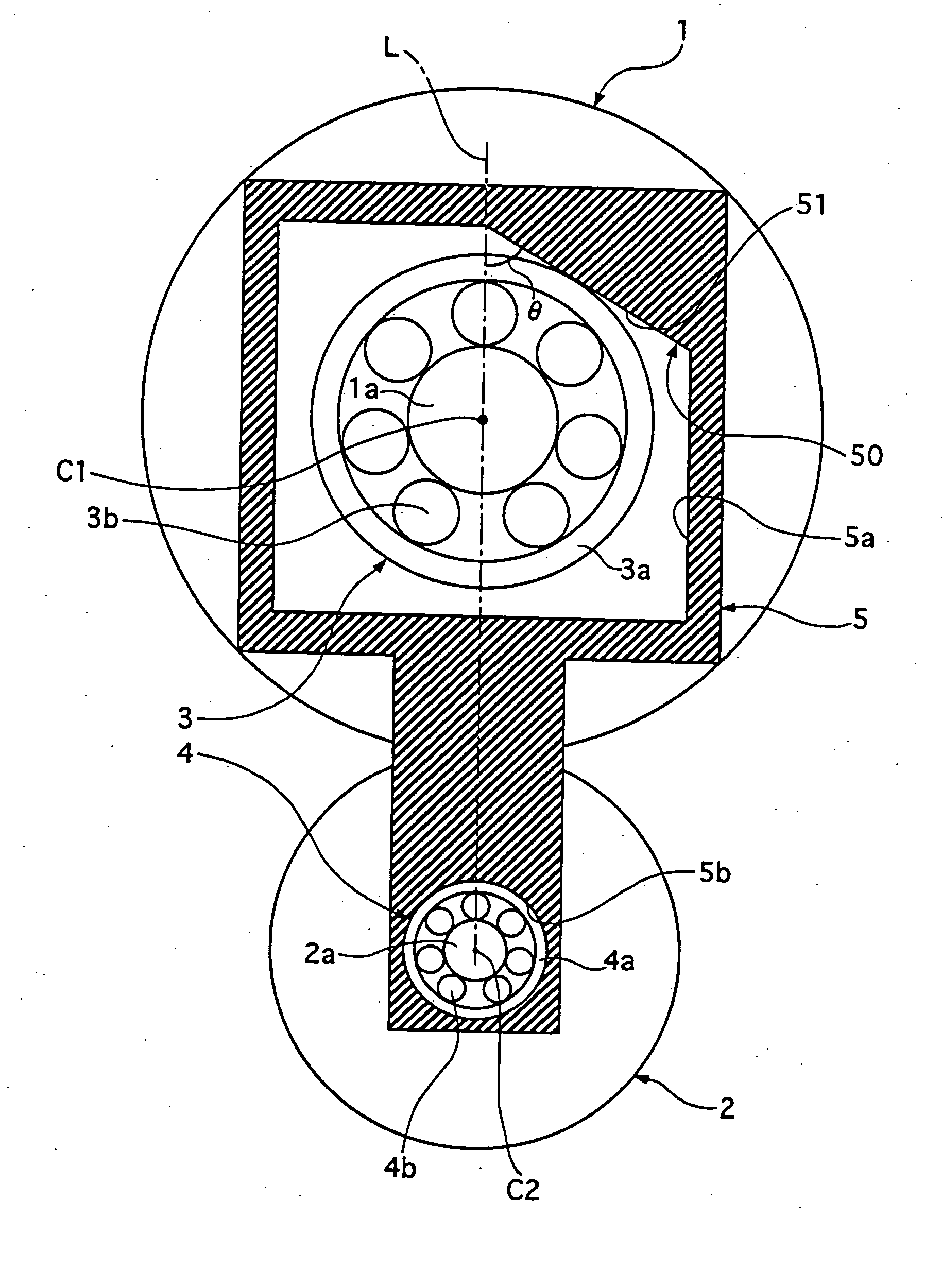
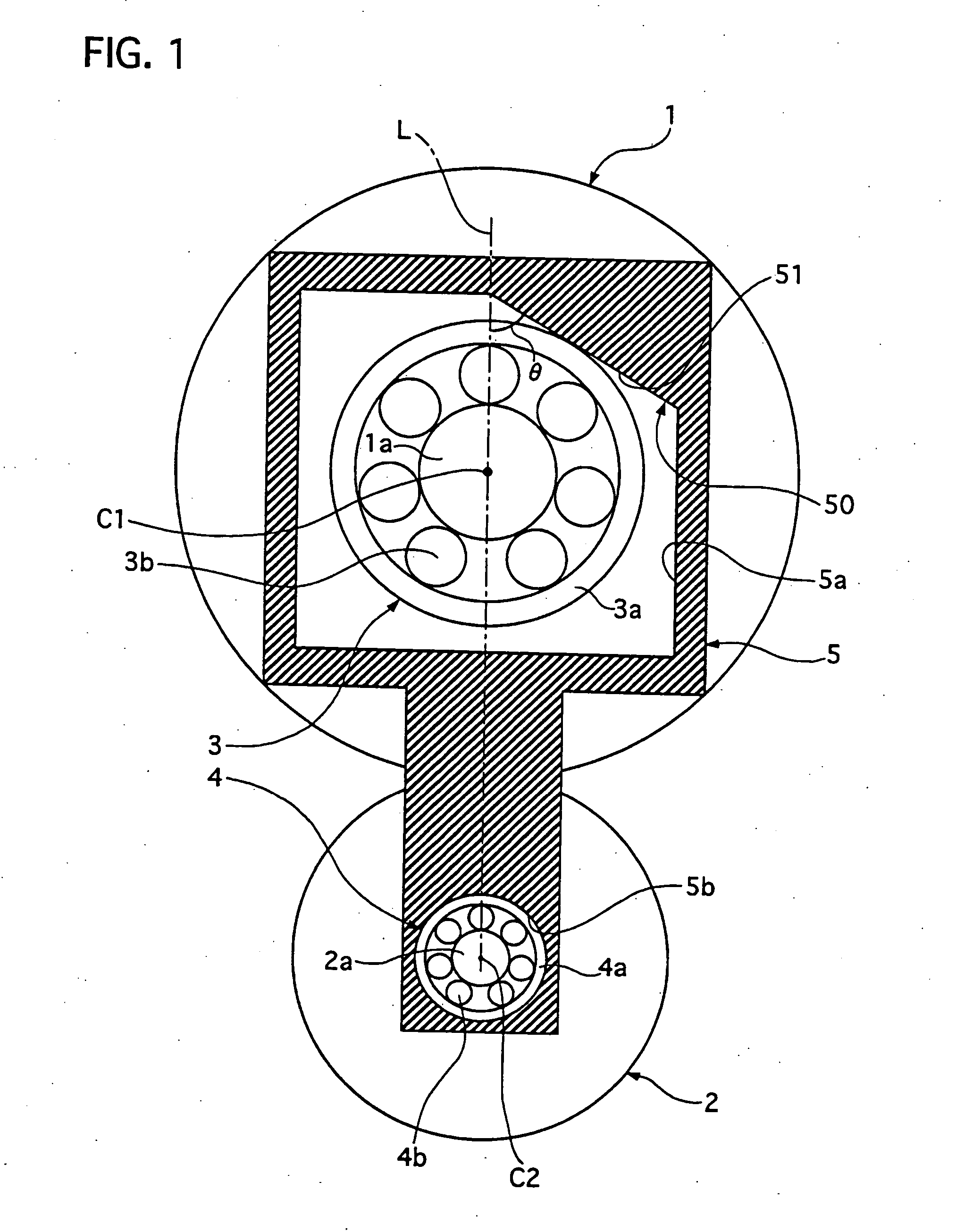
[0041] The friction drive device of the first embodiment has advantages in that the rollers 1 and 2 are pressed by the press force proportional to the drive torque TD without a complicate structure, improving its duration of life and power transmission efficiency. In addition, in this drive device, the roller bearing 3 can reduce the friction force caused between its outer race 3a of the bearing 3 provided on the drive roller 1 and the cam 50 formed on the frame member 5, which prevents decrease of the press force between the rollers 1 and 2.

second embodiment

[0042] Next, a friction drive device of the present invention will be described with the accompanying drawing of FIG. 4.

[0043] This friction drive device is equipped with a frame member 5 formed with a cam 5 having a first cam slope 51 and a second cam slope 52. The first cam slope 51 is formed similarly to the cam slope 51 of the cam 50 of the first embodiment shown in FIG. 1, while the second cam slope 52 is formed symmetrically to the came slope 52 with respect to a center connecting line L when the transmission torque is zero. The other parts of the drive device are similar to those of the drive device of the first embodiment shown in FIG. 1.

[0044] When the drive roller 1 applies drive torque in a first direction indicated by an arrow D1, an outer race 3a of a roller bearing 3 provided on the drive roller 1 is depressed onto the first cam slope 51, while the drive roller 1 applies drive torque in a second direction opposite to the first direction, the outer race 3a is depressed...

third embodiment

[0046] Next, a friction drive device of a third embodiment will be described with the accompanying drawing of FIG. 5.

[0047] This friction drive device is equipped with a frame member 5 formed at its other side portion, a lower side portion of the frame member 5 shown in FIG. 5, with a cam 5A having a third cam slope 53 and a fourth cam slope 54. These cam slopes 53, and 54 are formed symmetrically to first and second cam slope 51 and 52 with respect to the middle point between a center C1 of a drive roller 1 and a center C2 of a driven roller 2. An outer race 4a of a roller bearing 4 provided on the driven roller 2 is contactable with at least one of the cam slopes 53 and 54. The other parts of the drive device are similar to those of the drive device of the second embodiment shown in FIG. 4.

[0048] When the drive roller 1 applies drive torque in a first direction indicated by an arrow D1, an outer race 3a of the drive roller 1 and the outer race 4a of the driven roller 2 are depres...


PUM


Abstract

A friction drive device includes a first roller with a support part, a second roller, and a cam member to support them. The second roller receives press force from the first roller at a contact point of them so as to transmit mechanical power therebetween. The cam member has a cam formed with a cam slope on which the support part of the first roller is pressed by reaction torque from the second roller that is caused by transmission torque applied from the first roller. The cam slope is formed to have an angle with respect a tangent line at the contact point so that the first roller is pressed by reaction force of the cam to apply the press force proportional to the transmission torque to the second roller.

Description

BACKGROUND OF THE INVENTION [0001] 1. Field of the Invention [0002] The present invention relates to a friction drive device that is equipped a drive roller and a driven roller that are pressed to contact with each other so as to transfer mechanical power between them at a reduction ratio or an overdrive speed ratio. [0003] 2. Description of the Related Art [0004] A friction drive device of this kind is disclosed in Japanese patent laying-open publication No. 2001-173743. In this drive device, a drive roller and a driven roller are pressed to contact with each other so that friction force caused at their contact point enables the rollers to transmit mechanical power between them. The press force are obtained by adjusting bolts of a roller support portion so that their center distance becomes smaller. [0005] Another friction drive device of this kind is disclosed in Japanese patent laying-open publication No. 2002-349654. This drive device has a wedge roller arranged between drive an...

Claims


Application Information

Patent Timeline
IPC IPC(8): F16H13/10F16H15/46
CPCF16H15/46F16H13/10F16H13/14
Inventor YAMAMOTO, TAKESHI
Owner NISSAN MOTOR CO LTD
Why Eureka
Try Eureka