This helps you quickly interpret patents by identifying the three key elements:
Problems solved by technology
Method used
Benefits of technology
[0020] The above objects are achieved in an illustrated embodiment of an article dispensing apparatus embodied, for example, as a vending machine, including a controllably positioned suction hose dispenser for retrieving articles from a storage area. In one embodiment, the article dispensing apparatus comprises a storage volume for storing a plurality of articles to be dispensed; an article extracting device including a free end for selectively grasping to and extracting an article from the storage volume; and a user interface and control apparatus for allowing a user of the dispensing apparatus to initiate an article dispensing operation, and to cause control
Problems solved by technology
Such machines generally suffer from numerous disadvantages, such as poor reliability due to mechanical failures, as well known by those skilled in this art.
Although robotic, and specifically suction-type lifting mechanisms are in common use in factory settings, where space limitations are generally relaxed, their use in tight confines, such as an article vending machine, has not gained wide acceptance.
Although the technique disclosed in this patent facilitates rapid and accurate programming of the vending machine during servicing, it can not prevent dispensing of an incorrect product due to erroneous loading of the product into the machine, e.g., such as due to either inadvertently or purposefully loading an incorrect product into an incorrect storage column.
However, it would be possible to relatively easily “trick” or cheat a vending machine of this type by, for example, disabling the bar code scanner at the input end of each storage column, or by holding a false bar code in front of the reader during refilling of that column with a different, maybe erroneous and possibly inferior, product.
By including a bar code reader at the product exit chute of the dispenser, it is significantly more difficult to “trick” or cheat the machine by purposefully restocking the machine with erroneous and possibly inferior product.
However, in this and the above noted JP4123194A2 patent, it would not be uncommon for the fixed position bar code scanner to fail to read and identify the bar codes on the articles as they
Method used
Image
Click on the blue label to locate the original text in one second.
Reading with bidirectional positioning of images and text.
Examples
Embodiment Construction
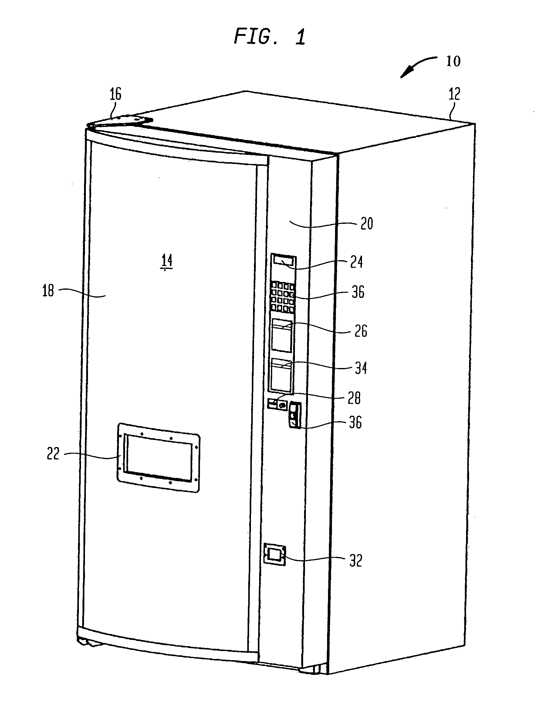
[0029]FIG. 1 illustrates an environment for the invention described herein, in the form of an article dispenser, such as a point-of-sale (POS) dispenser. Although throughout the following description, reference is made to implementation of the invention in a vending machine environment, it is intended that the term “vending machine”, and in fact the environment for the present invention, include more general purpose article handling, retrieval and / or dispensing apparatus, as well as POS equipment. Such equipment, if embodied as a portable device may comprise and be about the size of a traditional vending machine or as large as a tractor-pulled trailer, and if embodied as a non-portable device may comprise and be embodied as an automated dispensing room or an area located in a permanent structure, such as in a building (aboveground or underground, and with or without interior walls or an enclosing cabinet). Furthermore, it is intended that the term “articles” or “products” include in...
PUM
Abstract
The present invention relates to improvements in the design and operation of an article dispensing apparatus used in conjunction with an article identification device, and is particularly useful in the environment of a vending machine. In one embodiment, the article dispensing apparatus comprises a storage volume for storing articles to be dispensed; an article extracting device including a free end for selectively grasping to and extracting an article from the storage volume; and a user interface and control apparatus for allowing a user of the dispensing apparatus to initiate an article dispensing operation, and to cause controlled movement of the article extracting device so that a selected article is extracted from the article storage area and moves along a common path to a point within the dispensing apparatus that is associated with a dispensing area of the dispensing apparatus. An article identification device, mounted at a point within the dispensing apparatus that is near the common path, is operated so as to provide identification scanning of an article while the article is still being grasped by the article extracting device and while the article is still being moved by the article extracting device, as the article moves along the common path during the dispensing operation.
Description
CROSS-REFERENCE TO RELATED APPLICATIONS [0001] This application claims priority of and is a continuation of U.S. patent application Ser. No. 09 / 998,989, filed Nov. 29, 2001, entitled ARTICLE IDENTIFICATION, which application claims priority of and is a continuation in part of: (i) PCT / US01 / 16853, filed May 23, 2001, entitled METHOD AND APPARATUS FOR INCLUDING ARTICLE IDENTIFICATION IN AN ARTICLE HANDLING DEVICE; (ii) PCT / US01 / 16893, filed May 23, 2001, entitled METHODS OF DOING THE BUSINESS OF MACHINE VENDING (which claims the benefit of U.S. Provisional Patent Application No. 60 / 257,316, filed Dec. 21, 2000, entitled METHOD AND APPARATUS FOR ARTICLE HANDLING, SUCH AS FOR A VENDING MACHINE); (iii) PCT / US01 / 16837, filed May 23, 2001, entitled METHOD AND APPARATUS FOR CONTROLLING A VENDING MACHINE; (iv) PCT / US01 / 16847, filed May 23, 2001, entitled METHOD AND APPARATUS FOR STORING ARTICLES FOR USE WITH AN ARTICLE HANDLING DEVICE; (v) PCT / US01 / 16846, filed May 23, 2001, entitled METHOD ...
Claims
Application Information
Patent Timeline
Application Date:The date an application was filed.
Publication Date:The date a patent or application was officially published.
First Publication Date:The earliest publication date of a patent with the same application number.
Issue Date:Publication date of the patent grant document.
PCT Entry Date:The Entry date of PCT National Phase.
Estimated Expiry Date:The statutory expiry date of a patent right according to the Patent Law, and it is the longest term of protection that the patent right can achieve without the termination of the patent right due to other reasons(Term extension factor has been taken into account ).
Invalid Date:Actual expiry date is based on effective date or publication date of legal transaction data of invalid patent.