Wheel frame re-equipping mechanism with a rotatable blade

a rotatable blade and reequipping mechanism technology, applied in the direction of wheel protection, vehicle components, transportation and packaging, etc., can solve the problems of failure to effectively drive the blade to rotate, failure to continuously rotate in any external rotation,

Inactive Publication Date: 2005-07-07
LIN ROCKY
View PDF8 Cites 13 Cited by
  • Summary
  • Abstract
  • Description
  • Claims
  • Application Information

AI Technical Summary

Benefits of technology

[0006] It is therefore a principal object of the invention to provide a wheel frame re-equipping mechanism having a blade member in that the blade member will be able to be simultaneously rotated through a wheel or a wheel frame in car to proceed, and it still can be continuously rotated in a while after the car is decelerated to stop. Furthermore, the present invention has been accomplished to eliminate the aforesaid problem, such as the over-light blade which will be rotated in arbitrary direction.

Problems solved by technology

However, due to too light plastic blade, it will be arbitrarily rotated in forward or contrary direction, and fail to be continuously rotated in any external rotated power.
Besides, in the car to proceed, it will cause the blade to swing due to airflow coming from multiple directions, thereby failing to effectively drive the blade to rotate.

Method used


Image

  • Wheel frame re-equipping mechanism with a rotatable blade
  • Wheel frame re-equipping mechanism with a rotatable blade
  • Wheel frame re-equipping mechanism with a rotatable blade

Examples


Embodiment Construction

[0018] Wherever possible in the following description, like reference numerals will refer to like members and parts unless otherwise illustrated.

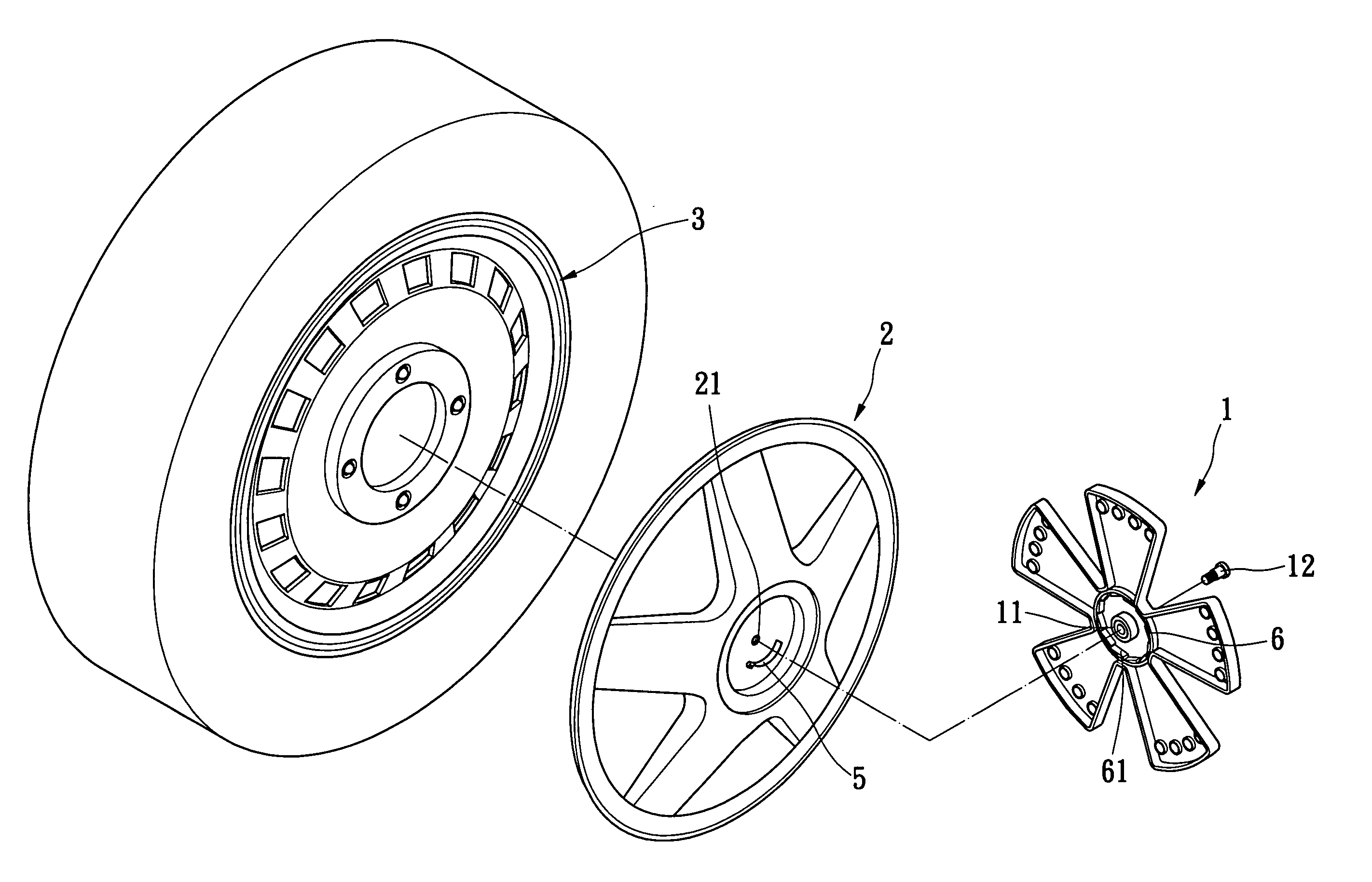
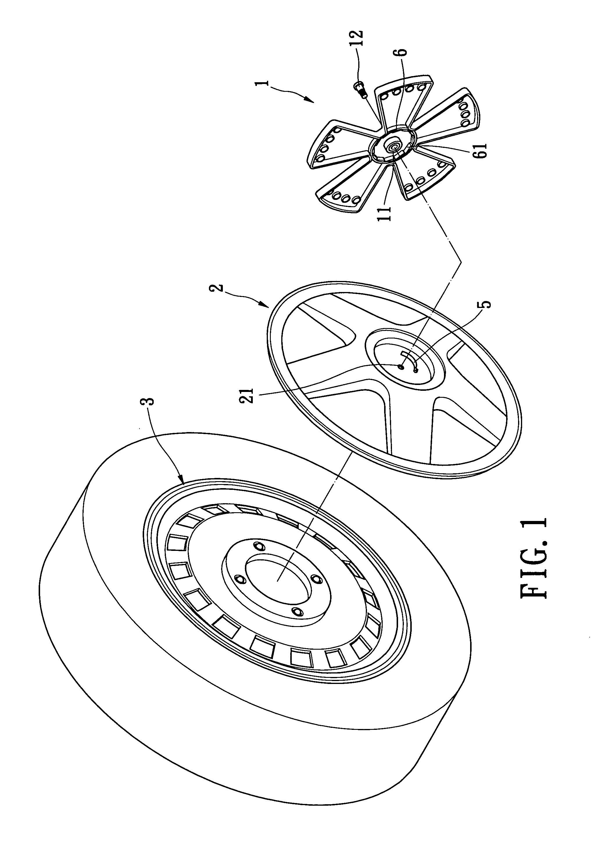
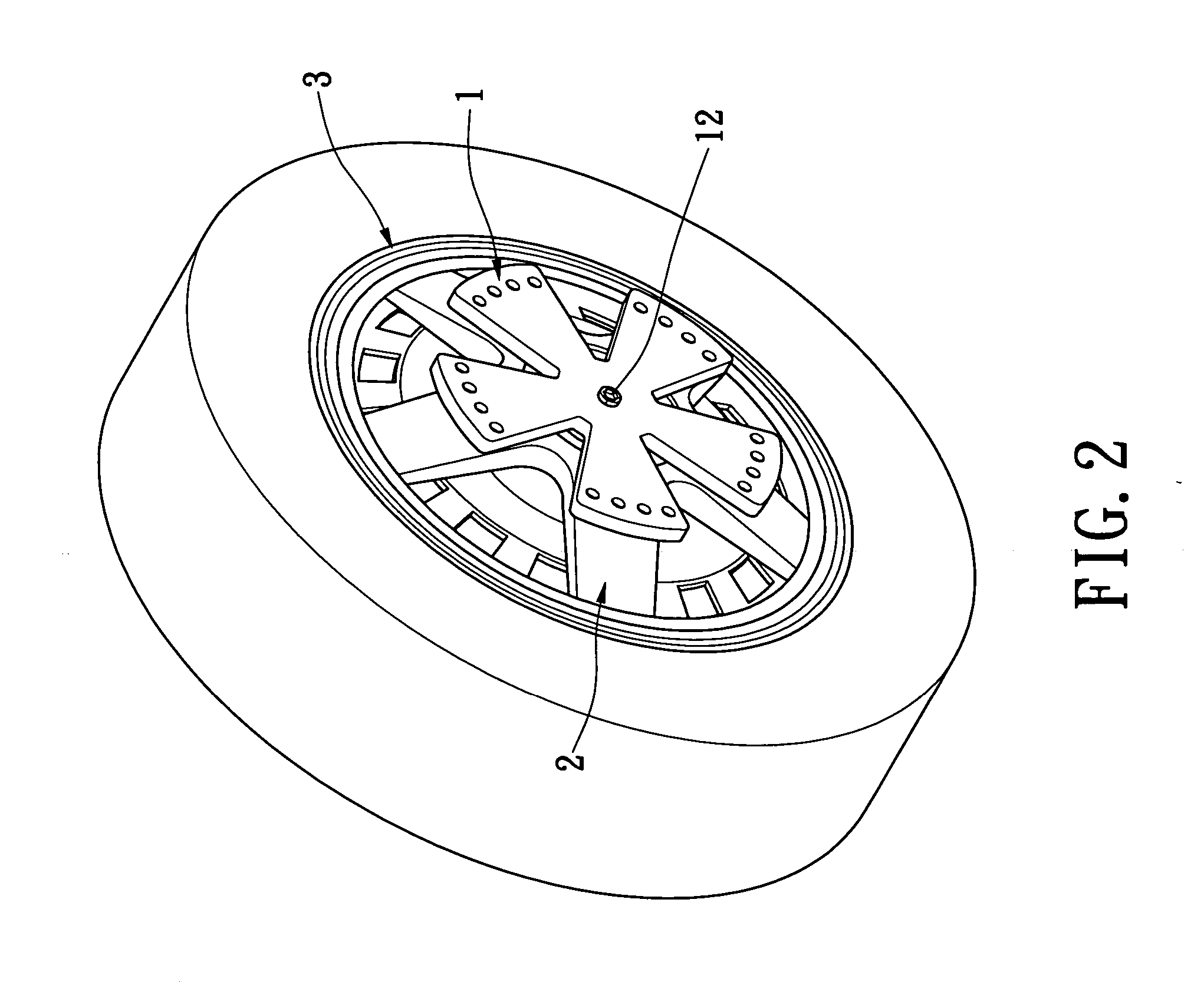
[0019] With reference to FIGS. 1 to 7, the present invention provides a wheel frame re-equipping mechanism including a wheel frame assembly, a blade member 1, a ratchet member 6 and an abutting member 5.

[0020] The present invention has at least two different embodiments. In a first embodiment, the ratchet member 6 is arranged on the blade member 1, and the abutting member 5 is arranged on the wheel frame assembly that can be a wheel frame cap 2 installed on one side of a wheel frame 3 (generally named as an iron frame). In a second embodiment, the ratchet member 6 is arranged on the wheel frame assembly that can be a wheel frame connection seat 8, and the abutting member 5 is arranged on the blade member 1 installed on an axial position of a wheel frame 7 (generally named as an aluminum frame).

[0021] The first embodiment of the present i...


PUM


Abstract

A wheel frame re-equipping mechanism includes a wheel frame assembly, blade member pivotally connected to the wheel frame assembly, a ratchet member having a hollow ring portion and a plurality of unidirectional teeth formed at an inner circumference of the hollow ring portion, and an abutting member abutting against one of the unidirectional teeth of the ratchet member. The ratchet member and the abutting member are arranged between the wheel frame and the blade member. Furthermore, the blade member will be able to be simultaneously rotated through a wheel or a wheel frame in car to proceed, and it still can be continuously rotated in a while after the car is decelerated to stop.

Description

BACKGROUND OF THE INVENTION [0001] 1. Field of the Invention [0002] The present invention relates to a wheel frame re-equipping mechanism with a rotatable blade and, more particularly to a wheel frame re-equipping mechanism having a blade member pivotally connected to a wheel frame cap or a wheel frame connection seat on a wheel frame. The blade member not only can provide a forward driving effect in car to proceed, but also can be continuously rotated in a while after the car is decelerated to stop. [0003] 2. Description of the Related Art [0004] In general, a conventional blade coaxially arranged on the wheel frame is formed of a metallic material with a great weight, such as an aluminum alloy material. It provides an object in that the blade can be rotated in car to proceed, and it still can be continuously rotated due to an inertia principle within a while after the car is decelerated to stop. [0005] In order to reduce cost and prevent weight of the blade re-equipped into the wh...

Claims


Application Information

Patent Timeline
Patent Type & Authority Applications(United States)
IPC IPC(8): B60B7/04
CPCB60B7/04
Inventor LIN, ROCKY
Owner LIN ROCKY
Why Eureka
Try Eureka