Method and apparatus for dynamic incremental defragmentation of memory

a memory and incremental defragmentation technology, applied in the field of computer memory management, can solve the problems of reducing the overhead of software, affecting the efficiency of memory defragmentation, so as to reduce the overhead of software and optimize the read barrier

Inactive Publication Date: 2005-07-07
IBM CORP
View PDF17 Cites 47 Cited by
  • Summary
  • Abstract
  • Description
  • Claims
  • Application Information

AI Technical Summary

Benefits of technology

[0012] Yet another application of the present invention is directed toward a software program for managing a memory heap for a processor running a time sensitive application. The software program includes a garbage collection routine. The garbage collection routine includes a defragmentation routine wherein used objects are moved from pages of memory containing a lowest amount of used objects to pages of memory containing a highest amount of used objects. The software sorts the pages of memory based on a number of dead objects on the pages. The garbage collection routine and the application are interleaved on a time-based or work-based schedule. The software divides the pages of memory into blocks of different size classes. Objects of larger block size classes are moved before blocks of the lower block size classes. A read barrier having a to-space invariant is included. A forwarding pointer is located in a header of each object. Optimizing software optimizes the read barrier to reduce its software overhead.

Problems solved by technology

Although the process of garbage collection frees memory it may be problematic in applications where its unpredictable consumption of processor time affects the running of the application.
In addition, the constant allocating and freeing of blocks of memory tends to fragment the memory over time.
Unfortunately, the mark-and-sweep technique has disadvantages.
One such disadvantage is that the sweep function of the mark-and-sweep technique examines every single memory block.
This is time consuming if the number of live objects is low relative to the number of objects allocated.
Unfortunately, prior art garbage collection routines cannot guarantee a given level of performance.

Method used


Image

  • Method and apparatus for dynamic incremental defragmentation of memory
  • Method and apparatus for dynamic incremental defragmentation of memory
  • Method and apparatus for dynamic incremental defragmentation of memory

Examples


Embodiment Construction

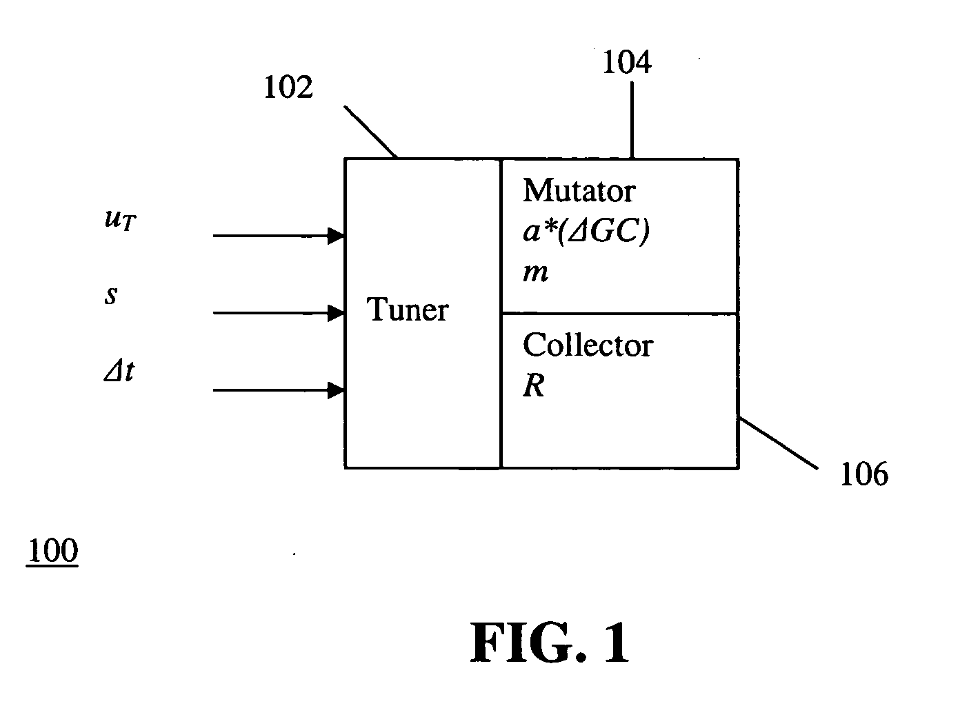
[0018] A collector constructed in accordance with a preferred embodiment of the present will provide guaranteed performance provided the application is correctly characterized by the user. In particular, the user must be able to specify the maximum amount of simultaneous live data, m, as well as the peak allocation rate over the time interval of a garbage collection a*(ΔGC). The collector is parameterized by its tracing rate R. Given these characteristics of the mutator and the collector, the user then has the ability to tune the performance of the system using three interrelated parameters: total memory consumption, minimum guaranteed CPU utilization and the resolution at which the utilization is calculated.

[0019] The relationship between these parameters is shown graphically in FIG. 1. The mutator 104 is characterized by its allocation rate over a garbage collection interval a*(ΔGC) and by its maximum memory requirement m. The collector 106 is characterized by its collection rate...


PUM


Abstract

A garbage collection process for managing a memory includes a defragmentation cycle. The garbage collection process is interleaved with a running application on a time-based or work-based schedule. The memory is divided into pages which are further divided into blocks falling into one of a number of block size classes. Objects that were not used during the last garbage collection phase are marked. Objects that were used are moved from pages containing the least live objects to pages containing the most live objects. Objects of the largest block size classes are moved first and objects of the smallest block size class are moved last. The garbage collection interval can be selected to satisfy desired CPU utilization or memory overhead requirements.

Description

CROSS-REFERENCE TO RELATED APPLICATIONS [0001] Not Applicable. STATEMENT REGARDING FEDERALLY SPONSORED-RESEARCH OR DEVELOPMENT [0002] Not Applicable. INCORPORATION BY REFERENCE OF MATERIAL SUBMITTED ON A COMPACT DISC [0003] Not Applicable. FIELD OF THE INVENTION [0004] The invention disclosed broadly relates to the field of computer memory management. More particularly, the present invention relates to a method and apparatus for defragmenting a memory without stopping the running of an ongoing application. BACKGROUND OF THE INVENTION [0005] With regard to computers, garbage collection refers to a process of identifying unused areas of main memory storage. In object-oriented computing languages, the computer executing the program allocates memory for each of the objects. A Java Virtual Machine (JVM) using the object oriented programming language Java allocates memory for the instantiation of the objects from a free memory area called a heap. Memory is allocated to, and freed from, th...

Claims


Application Information

Patent Timeline
Patent Type & Authority Applications(United States)
IPC IPC(8): G06F12/00G06F12/02
CPCG06F12/0269
Inventor BACON, DAVID FRANCISCHENG, PERRYRAJAN, VADAKKEDATHU THOMAS
Owner IBM CORP
Why Eureka
Try Eureka