Cartridge for stapler and stapler

a stapler and stapler technology, applied in the field of staplers, can solve the problems of poor design of staples, difficulty in correct binding, and disc-like pattern parts of staples on the shoulder parts of staples, and achieve the effect of enlarge the shape of the pattern part and firmly bind the sheet materials

Inactive Publication Date: 2005-07-14
KAMEYAMA TOSHIYUKI
View PDF11 Cites 910 Cited by
  • Summary
  • Abstract
  • Description
  • Claims
  • Application Information

AI Technical Summary

Benefits of technology

[0009] Moreover, the staple with a different pattern part is inserted to the cartridge, so that sheets of paper can be bound with the staple with the different pattern part by replacement of the cartridge and a good looking appearance can be enjoyed.
[0016] In this way, the staple pusher includes the take-out section that guides the staple in the storing section to the take-out opening and the pressing section that causes the leg pats to stand at the take-out opening, thereafter abutting against the shoulders to push out the staple from the take-out opening. Accordingly, even when the leg parts are arranged to be inclined against the face along the guide groove part in the storing section, the shoulder parts can be pushed down in the perpendicular direction after the leg parts are positioned perpendicularly, and the leg parts can be correctly pierced through the sheet materials, thereby making it possible to firmly bind the sheet materials with the staple.
[0017] Moreover, since the pattern part is structured to be pushed by the staple pusher, there is no need to take the shoulder parts of the staple widely, thereby making it possible to enlarge the shape of the pattern part by the corresponding amount.

Problems solved by technology

However, since the conventional staple is structured to have only a shape indispensable for ensuring a sheet binding function, the exposed portion is limited to a linear shape, so that the staple is poor in design.
However, the staple having the disc-like pattern part on the shoulder parts is of little practical use since a large number thereof cannot be stored in a cartridge at one time because of its shape.
Moreover, in the case of storing the multiple staples each having the pattern part, since the pattern parts of the adjacent staples interfere with each other, the leg portions of the staple must be stored in an oblique direction to a face along a guide groove part.
If the staple is pushed out from a take-out opening as it is, trouble is caused in piercing the leg parts through the sheet material to generate difficulty in performing correct binding.

Method used


Image

  • Cartridge for stapler and stapler
  • Cartridge for stapler and stapler
  • Cartridge for stapler and stapler

Examples


second embodiment

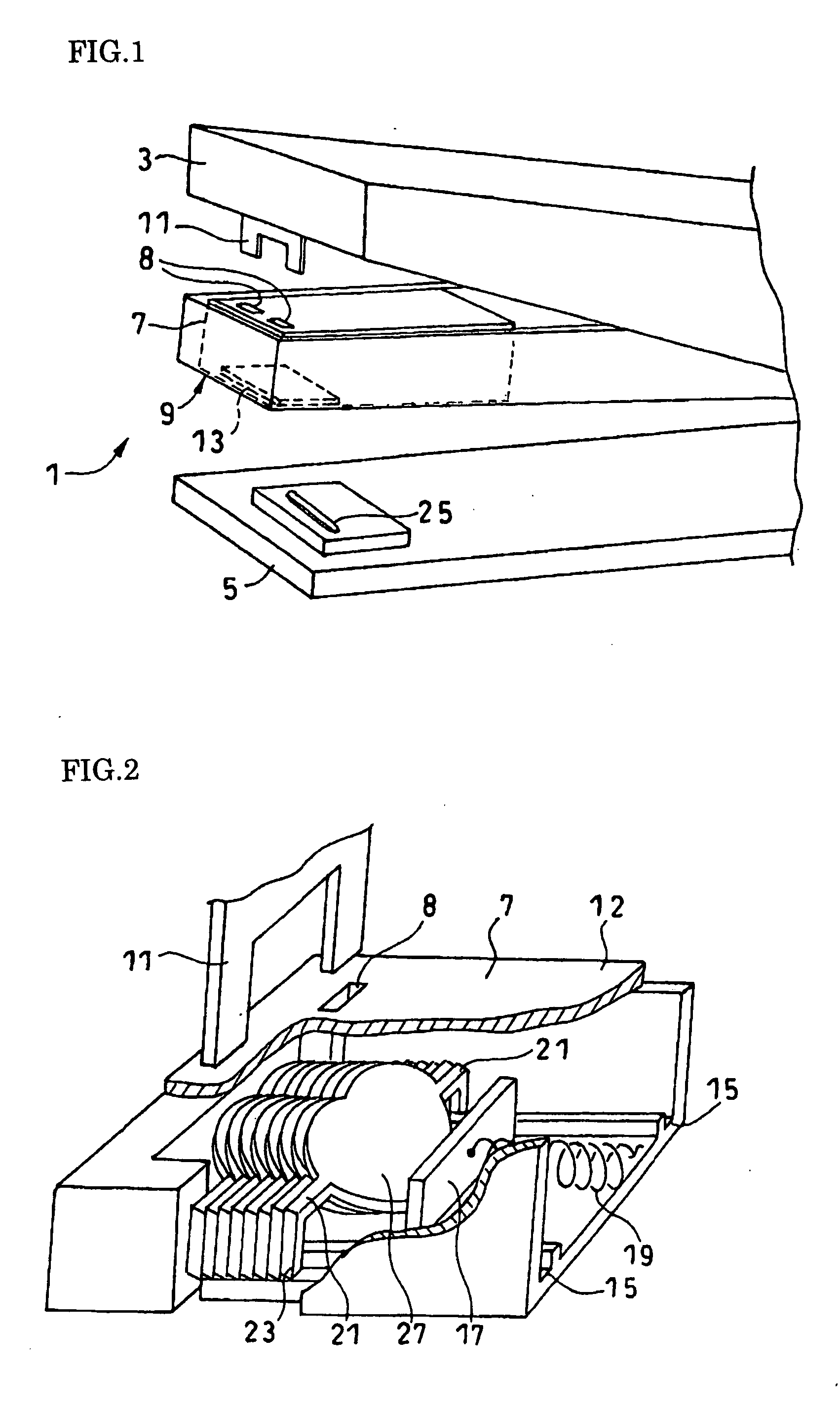
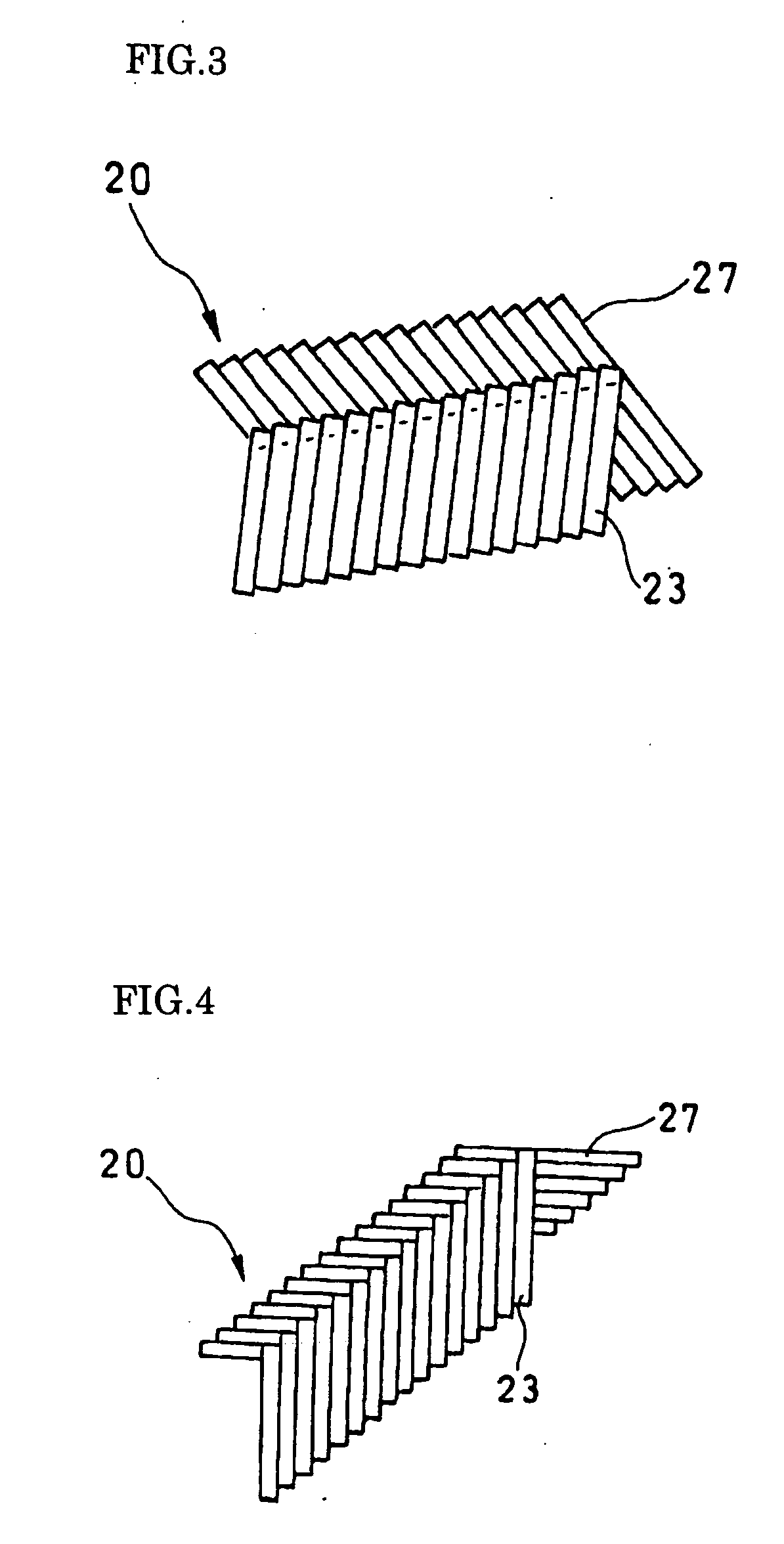
[0036]FIG. 1 is a perspective view schematically illustrating a stapler according to an embodiment of the present invention; FIG. 2 is a perspective view illustrating a structure of a cartridge of FIG. 1; FIG. 3 is a side view of staples stored in the cartridge of FIG. 2; FIG. 4 is a side view illustrating a modification of the staples of FIG. 3; FIG. 5 is a perspective view illustrating a stapler according to the present invention; FIG. 6 is a side view illustrating staples to be stored in the cartridge of FIG. 5; and FIG. 7 is a front view of each staple in a state that sheets of paper are bound.

first embodiment

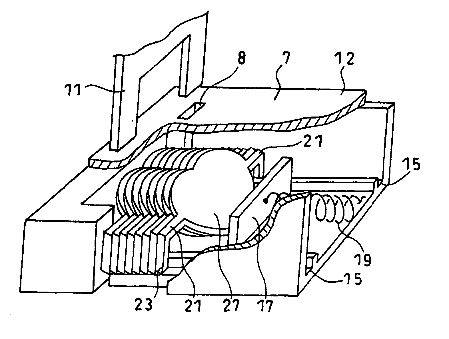
[0037] A stapler 1 includes a staple receiving base 5 and a retaining part 3 having a staple pusher 11 rotatably provided at an end portion side of the receiving base 5, and a staple storing section 9 is provided between the receiving base 5 and the retaining part 3, and a cartridge 7, which has multiple staples 20 for the stapler 1 stored in parallel, is attached to the storing section 9.

[0038] The retaining part 3 includes the staple pusher 11 that pushes out the staple 20 stored in the cartridge 7 to a take-out opening 13, and a central portion of the staple pusher 11 is notched so that the staple pusher 11 abuts against shoulder parts 21 of the staple according to the present invention.

[0039] The receiving base 5 has a groove-like bending section 25 that is placed at a position opposite to the staple pusher 11 of the retaining part 3 and bends leg parts 23 of the staple 21.

[0040] The cartridge 7 has the take-out opening 13 for staple 20 on one side of a case 12. Moreover, a g...

fifth embodiment

[0059] A modification of the fifth embodiment is next explained. As illustrated in FIG. 12(a), in this modification, a twist is formed in the shoulder parts 21 of the staple 20. The twist is formed by axially rotating the shoulder parts 21 in a direction illustrated by an arrow A, so that the pattern part 27 is easily rotated in the direction illustrated by the same arrow A. In this way, since the twist is formed in the shoulder parts 21, the pattern part 27 can be easily changed from the inclination state against the surface of the sheet material 60 to the parallel state, so that an extra force is not required at the time of binding the sheet materials 60 and a smooth binding operation can be obtained. In addition, it is desirable that the length of the twisting portion should be short as much as possible. Since a portion of the shoulder parts 21 in which no twist is formed is flat on its upper surface, the staple pusher 11 easily comes in contact therewith and the staple 20 is smo...


PUM


Abstract

A stapler (1) of the present invention includes a retaining part (3) having a staple pusher (11), a storing section (9) that stores a staple (20), and a receiving base (5) that hat bents leg parts (23) after piercing the staple (2) pushed out by the staple pusher (11) through a sheet material to bind the sheet material (60) with the staple (20). The staple (20) includes left and right shoulder parts (21) against which the staple pusher (11) abuts, leg parts (23) extending substantially perpendicularly from the shoulder parts (21) and a pattern part (27) having an arbitrary shape and provided between the left and right shoulder parts (21). The pattern part (27) is inclined against the leg parts (23) and the storing section (9) is provided, on one side thereof, with a take-out opening (13) of the staple (20) that is large enough to allow the pattern part (27) to pass.

Description

TECHNICAL FIELD [0001] The present invention relates to a stapler that binds multiple sheet materials. BACKGROUND ART [0002] Conventionally, a staple for a stapler includes shoulder parts exposed to a surface of a sheet material and leg parts extending substantially perpendicularly from both ends of the shoulder parts. In a state that the leg parts pierces through the multiple sheet materials, they are bent at the rear side of the sheet to bind the multiple sheet materials. [0003] However, since the conventional staple is structured to have only a shape indispensable for ensuring a sheet binding function, the exposed portion is limited to a linear shape, so that the staple is poor in design. [0004] While, Japanese Patent Laid-Open No No. 6-173917 discloses one in which a disc-like pattern part is formed on the shoulder parts. [0005] However, the staple having the disc-like pattern part on the shoulder parts is of little practical use since a large number thereof cannot be stored in ...

Claims


Application Information

Patent Timeline
Patent Type & Authority Applications(United States)
IPC IPC(8): B25C1/00B25C5/02F16B15/00F16B15/02F16B15/08
CPCB25C1/005B25C5/02Y10S411/92F16B15/02F16B15/08F16B15/0015B25C5/16
Inventor KAMEYAMA, TOSHIYUKIKAMEYAMA, SANNOSUKE
Owner KAMEYAMA TOSHIYUKI
Why Eureka
Try Eureka