Tool box power center

Inactive Publication Date: 2005-07-21
KRIEGER MICHAEL
View PDF3 Cites 63 Cited by
  • Summary
  • Abstract
  • Description
  • Claims
  • Application Information

AI Technical Summary

Problems solved by technology

At the remote locations, the tools battery supply may become depleted or an electrical outlet may

Method used


Image

  • Tool box power center
  • Tool box power center
  • Tool box power center

Examples


Embodiment Construction

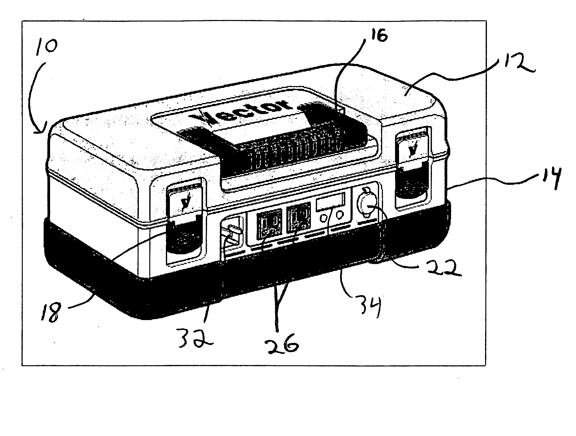
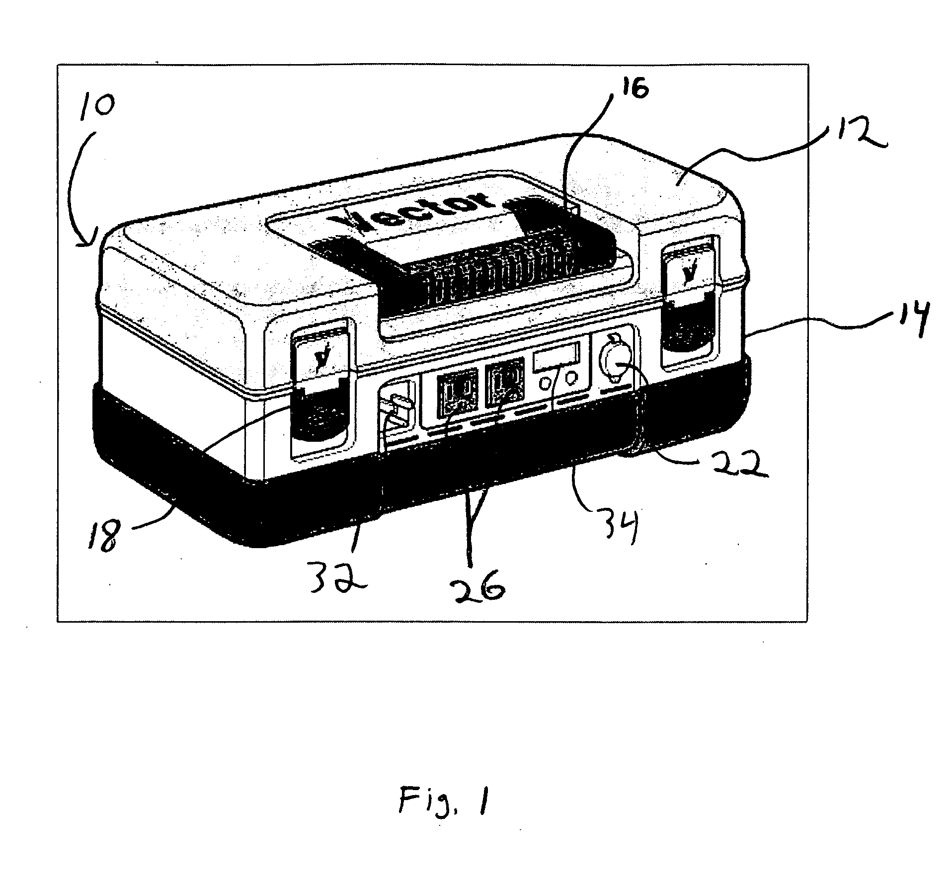
[0011] The portable power center shown in FIG. 1 includes a housing 10. In the embodiment illustrated, the housing takes to form of a tool box having a lid 12 and a base 14. The lid 12 may be opened or closed to expose or enclosed a cavity within the housing 10. The cavity may be used to store tools or other items. The lid 12 may be provided with a handle 16 that may be used to carry the power center. Latches 18 or other securing devices may be provided on the lid 12 to secure the lid 12 in the closed position on the base 14.

[0012] Compartments, drawers, and the like can be provided on and within the housing 10 to provide storage for accessories and tools. The housing 10 includes an easy to grasp handle 16 that allows the power center to be moved about. Additionally, wheels and / or a large carrying strap can be provided for easy of portability and transporting the power center.

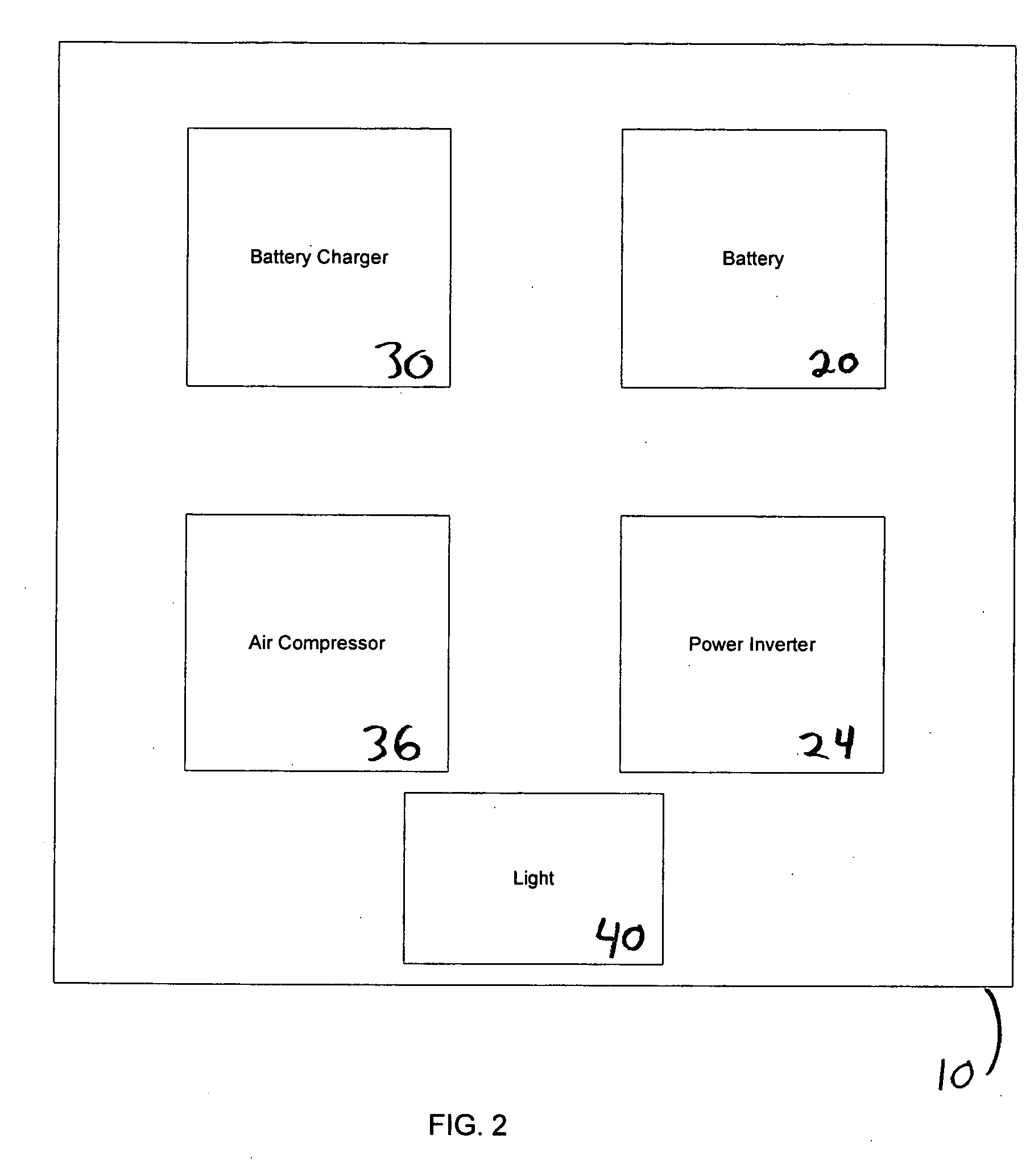
[0013] A power source 20, for example a battery, such as a sealed lead acid battery, a nickel cadmium batt...


PUM


Abstract

A “tool box” style power center is provided. The power center may be designed as a versatile, portable power center addressing the most common needs of power for a consumer. The power center preferable can provide DC power, AC power, battery charging capability, the capability to jumpstart a vehicle with a depleted battery, and other power providing capabilities. The power center includes a housing that is adapted to be used as a toolbox. The housing can include various compartments and the like to house accessories and tools.

Description

BACKGROUND OF THE INVENTION [0001] Hand tools such as saws, drills, screwdrivers, nail guns, etc. are now often power driven. These tools may be powered by battery or from an electrical outlet. A tool box is typically used to store the hand tools and to transport the tools to remote locations. At the remote locations, the tools battery supply may become depleted or an electrical outlet may not be available. In these circumstances, the power features of the hand tools are rendered useless. [0002] Thus, there is a need for a device that can address the power needs generated by modern power tools and other consumer power requirements. SUMMARY OF THE INVENTION [0003] In an exemplary embodiment of the invention, a “tool box” style power center is provided. [0004] The power center may be designed as a versatile, portable power center addressing the most common needs of power for a consumer. The power center preferable can provide DC power, AC power, battery charging capability, the capabi...

Claims


Application Information

Patent Timeline
IPC IPC(8): H01M50/202H01M50/247H01M50/296H02J7/00
CPCH01M2/1022H02J2001/006H02J7/0042H02J1/122Y02E60/10H01M50/247H01M50/202H01M50/296
Inventor KRIEGER, MICHAEL
Owner KRIEGER MICHAEL
Why Eureka
Try Eureka