System and method for ground fault detection and interruption

a ground fault and system technology, applied in the field of system and method for ground fault detection and interruption, to achieve the effect of safe and effective decoupling

Inactive Publication Date: 2009-07-30
AES GLOBAL HLDG PTE LTD
View PDF8 Cites 209 Cited by
  • Summary
  • Abstract
  • Description
  • Claims
  • Application Information

AI Technical Summary

Benefits of technology

[0006]In another embodiment the invention may be characterized as a method to ensure that a ground fault detector and interrupter is operating correctly. The invention in this embodiment includes introducing a known signal into the input of a ground fault detector and interrupter, sensing whether the known signal at the output of the ground fault detector and interrupter is present, and then branching depending on whether the known signal is present at the output of the ground fault detector and interrupter: If the known signal is present, then filtering out the known signal and transmitting the filtered signal to the inverter; but if the known signal is not present, then decoupling the PV array from the rem

Problems solved by technology

If the known signal is not sensed at the output of the ground fault detector and interrupter, then that indicates that the ground fault detector and interrupter

Method used


Image

  • System and method for ground fault detection and interruption
  • System and method for ground fault detection and interruption
  • System and method for ground fault detection and interruption

Examples


Embodiment Construction

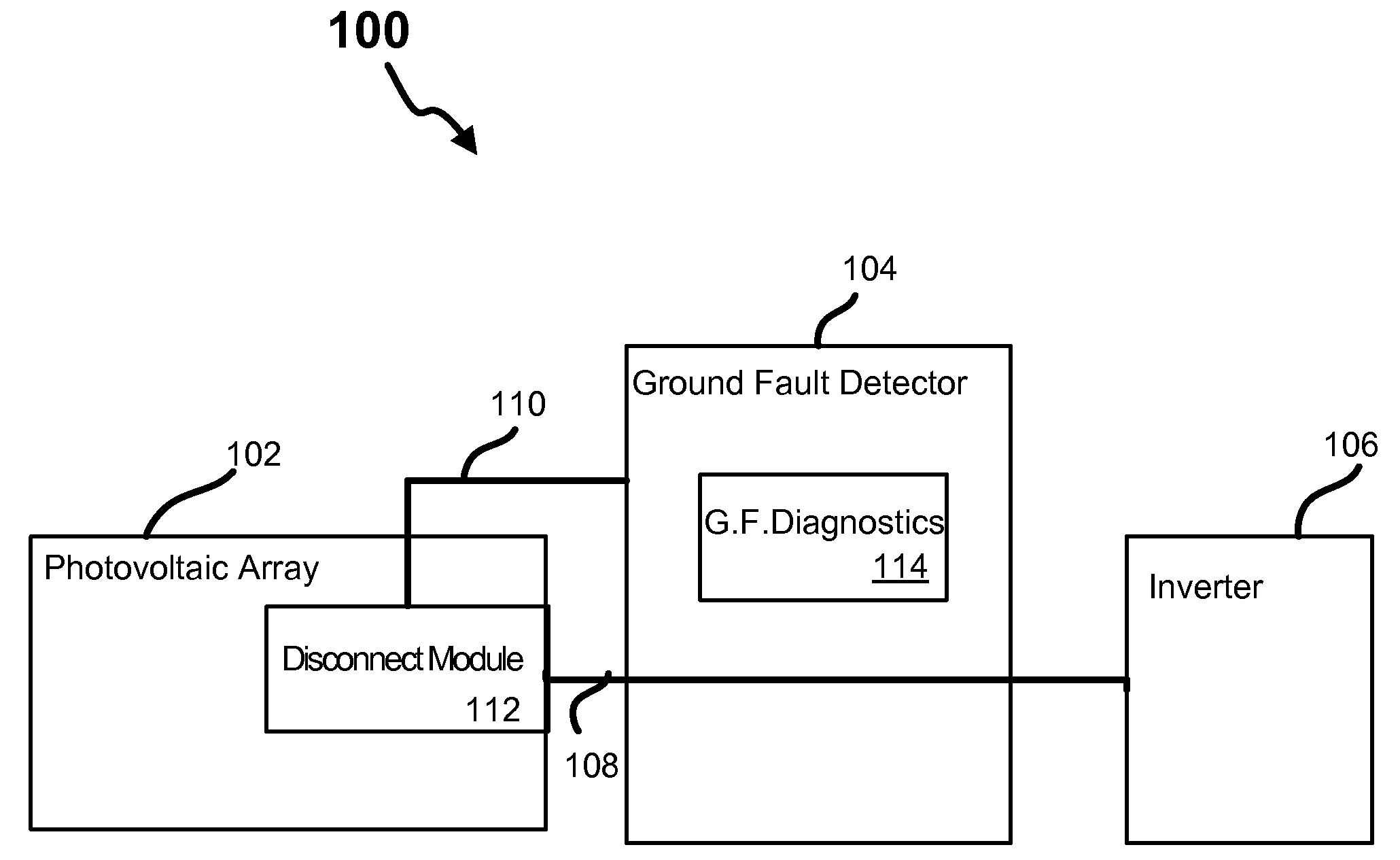
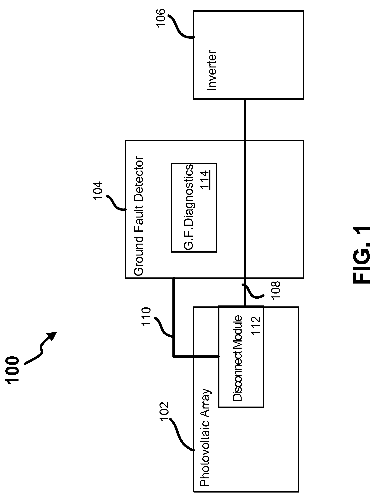
[0018]Referring now to the drawings, where like or similar elements are designated with identical or corresponding reference numerals throughout the several views, and referring in particular to FIG. 1, shown is a block diagram depicting a photovoltaic power conversion system 100 that includes a photovoltaic array 102 coupled to an inverter 106. Coupled between the photovoltaic array 102 and the inverter 106 is a ground fault detector and interrupter 104. Conductor lines 108 couple the photovoltaic array 102 to the inverter 106, and the ground fault detector and interrupter 104 is coupled (e.g., inductively coupled) to the conductor lines 108. As shown, the ground fault detector and interrupter 104 includes a diagnostics portion 114, and the ground fault detector and interrupter 104 is coupled to a disconnect module 112 via a ground fault signal line 110.

[0019]It should be recognized that the illustrated arrangement of the components depicted in FIG. 1 is logical and not meant to be...


PUM


Abstract

A ground fault detector and interrupter for a photovoltaic (PV) energy conversion system, method and apparatus are disclosed. In an exemplary embodiment, the system includes first and second inputs adapted to couple to a first and second rails of a PV array. An inverter is configured to convert DC power generated from the PV array to AC power. A ground fault detector and interrupter, which is coupled to the first and second rails and to the inverter, is configured to detect ground fault conditions in the PV array and to decouple the PV array from the remaining portion of the PV energy conversion system upon such detection. A known signal is coupled to the input of the ground fault detector and interrupter, and then sensed at the output of the ground fault detector and interrupter to determine whether components of the ground fault detector and interrupter are operating properly.

Description

FIELD OF THE INVENTION[0001]This invention relates generally to apparatus and methods for converting solar energy to electrical energy, and more specifically to apparatus and methods for reliably detecting unsafe ground fault conditions and interrupting operation of such energy conversion systems when unsafe ground fault conditions are detected.BACKGROUND OF THE INVENTION[0002]The transformation of light energy into electrical energy using photovoltaic (PV) systems has been known for a long time and such photovoltaic energy conversion systems are increasingly being implemented in residential, commercial, and industrial applications. Rapid detection of unintended shunting of DC current to ground, also known as a ground fault, is mandatory for implementation of such systems because ground faults present potentially dangerous conditions, including fire risk. Accordingly, for safety reasons photovoltaic energy conversion systems must rapidly detect ground fault conditions and automatica...

Claims


Application Information

Patent Timeline
IPC IPC(8): H02H3/00H02J1/00H01H83/00
CPCH02H7/1222H02H7/20H01L31/02021G01R31/024H01H83/04H02H3/335Y02E10/50G01R31/327G01R31/52
Inventor GILMORE, JACK A.SEYMOUR, ERIC
Owner AES GLOBAL HLDG PTE LTD
Why Eureka
Try Eureka